Bolt holes look simple until the parts reach assembly. On the drawing, the bolt diameter is known, the hole is there, and the joint seems straightforward. In production, the hole can still be wrong for the job. The bolt may not pass through easily. A stack of parts may refuse to line up. Painted parts may scrape. Hardware may go in only after force is applied.
Most of these problems are not caused by the bolt itself. They come from choosing hole clearance without thinking far enough ahead. A clearance hole is not just a hole that is larger than the fastener. It is a feature that has to absorb variation from machining, coating, part stack-up, and real assembly conditions.
That is why clearance-hole design deserves more attention than it usually gets. A hole that is technically large enough may still be poor for production, while a hole that is more generous than necessary may solve one problem and create another. In most CNC assemblies, normal fit is the best starting point. Close fit makes more sense when bolt guidance matters, while loose fit is often the better choice for coated parts, stacked assemblies, or jobs with more real-world variation.
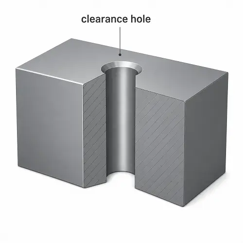
What Is a Clearance Hole?
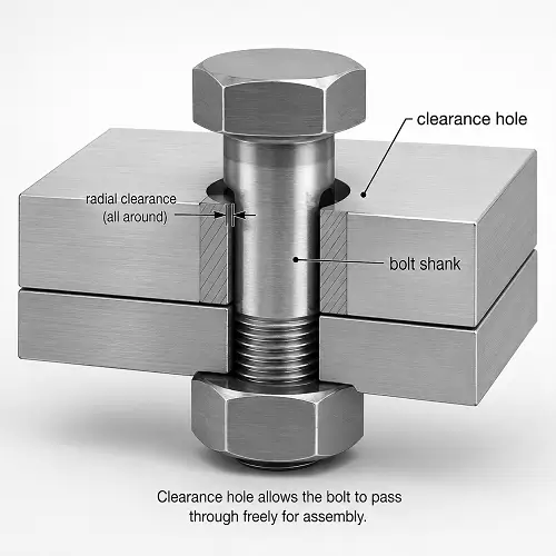
A clearance hole allows a bolt, screw, or similar fastener to pass through the part without engaging threads in that hole. The fastener does not lock into the hole itself. Clamping is created somewhere else, usually by a nut or by a threaded feature in another part.
That distinction matters because a clearance hole is not the same as a tapped hole and not the same as a press-fit hole. A tapped hole is meant to carry the thread. A press-fit hole is meant to control interference and retention. A clearance hole is meant to provide enough room for the fastener to pass through while still keeping the assembly practical and controlled.
The phrase “enough room” is where the real design decision begins.
Why Clearance Holes Matter in Real Assembly
A clearance hole affects more than whether the bolt physically fits. It affects how parts align, how easily the assembly goes together, and how much variation the joint can tolerate before operators start fighting the hardware.
Too little clearance creates obvious trouble. Bolts bind in the hole. Parts have to be shifted by hand. Painted surfaces scrape. Assemblies that looked fine in CAD suddenly require drift pins, pry bars, or forced alignment.
Too much clearance causes a different kind of trouble. The hardware drops in easily, but the joint loses guidance. The bolt can float more than intended. Washers may sit too close to the edge of the hole. A joint that needed some positional control now depends more heavily on friction or secondary features.
This is why clearance holes should not be chosen from habit alone. The correct size depends on what the bolt is doing in the assembly and how much variation the design must survive.
Close Fit, Normal Fit, and Loose Fit
Most clearance-hole decisions fall into three practical categories: close fit, normal fit, and loose fit. These are not just size labels. They describe how much assembly freedom the fastener is allowed.
Close Fit
A close-fit hole gives the fastener only a small amount of room beyond nominal diameter. This is useful when the bolt helps guide the parts into position or when the pattern relationship is already tightly controlled.
Close fit can work well on small part counts and clean machined assemblies. It becomes less forgiving when coatings are thick, stacks are larger, or hole position variation is already tight.
Normal Fit
A normal-fit hole is the best default for many CNC assemblies. The bolt has enough room to pass through without creating constant assembly resistance, but not so much room that the joint starts to feel uncontrolled.
Normal fit usually makes the most sense when the bolt is mainly there to clamp, not to act as the primary locating feature.
Loose Fit
A loose-fit hole is used when real-world variation is larger and easier assembly matters more than tight guidance. This is common on coated parts, larger stacked assemblies, mixed-manufacturing assemblies, or hardware that has to go together quickly on the floor.
Loose fit is not sloppy design by default. Loose fit is often the right answer when the joint needs more tolerance to real production variation.
Fit Comparison
| Fit type | Typical use | Main advantage | Main risk |
|---|---|---|---|
| Close fit | Controlled assemblies, fewer stacked parts, tighter hole relationships | Better guidance, less bolt float | Harder assembly if variation is present |
| Normal fit | General CNC assemblies, ordinary bolted joints | Best balance of control and assembly ease | May still be too tight for coated or stacked parts |
| Loose fit | Coated parts, thicker stacks, mixed-part assemblies, faster installation | Easier bolt insertion | Less positional control |
Common Metric Clearance Hole Sizes
Most machining teams need more than a definition. They need a practical starting size. The table below gives common working values for standard metric fasteners using close, normal, and loose fit logic.
| Fastener size | Close fit | Normal fit | Loose fit |
|---|---|---|---|
| M3 | 3.2 mm | 3.4 mm | 3.6 mm |
| M4 | 4.3 mm | 4.5 mm | 4.8 mm |
| M5 | 5.3 mm | 5.5 mm | 5.8 mm |
| M6 | 6.4 mm | 6.6 mm | 7.0 mm |
| M8 | 8.4 mm | 9.0 mm | 10.0 mm |
| M10 | 10.5 mm | 11.0 mm | 12.0 mm |
| M12 | 13.0 mm | 13.5 mm | 14.5 mm |
These values are useful starting points, not blind rules. A normal-fit M8 hole may work perfectly on a single machined plate and still be too tight once paint, plating, and stack-up are added to the real assembly.
Common Inch Clearance Hole Sizes
Inch hardware should be treated the same way. The drill size follows the fit decision, not the other way around.
| Fastener size | Close fit | Normal fit | Loose fit |
|---|---|---|---|
| #10 | 0.196 in | 0.201 in | 0.221 in |
| 1/4 in | 0.257 in | 0.266 in | 0.281 in |
| 5/16 in | 0.323 in | 0.332 in | 0.344 in |
| 3/8 in | 0.390 in | 0.406 in | 0.438 in |
| 1/2 in | 0.515 in | 0.531 in | 0.562 in |
Again, these numbers help you start the conversation. They do not replace assembly judgment.
When Normal Fit Is Usually the Best Default
Normal fit is usually the best starting point when the bolt is mainly used for clamping, the assembly has a modest number of parts, and the bolt is not expected to act like a locating pin.
That covers a large portion of ordinary CNC work: covers, brackets, machine plates, housings, and general bolted joints where the hardware primarily creates clamp load and the real positional control comes from the part geometry, not from the bolt shank.
Designers often jump too quickly to close fit because it sounds more precise. In practice, close fit can create more assembly trouble than value if the joint already has enough control elsewhere. In many cases, normal fit is the better engineering choice because it gives the assembly some breathing room without giving away too much control.
How to Choose the Right Fit
The most useful question is not “what drill size matches this bolt?” The real question is “how much variation must this assembly survive and still go together cleanly?”
Choose close fit when the hardware helps guide the assembly and the parts are already well controlled.
Choose normal fit when the hardware mainly clamps and the assembly is not unusually sensitive.
Choose loose fit when coatings, part stack-up, mixed processes, field assembly, or larger positional variation make insertion more difficult in real life than it looks in CAD.
Quick Decision Table
| Situation | Better starting choice |
|---|---|
| Single machined plate, controlled pattern, bolt helps guide assembly | Close or normal fit |
| General bolted joint, bolt mainly provides clamp load | Normal fit |
| Painted or coated parts | Normal or loose fit |
| Multi-part stack with accumulated position variation | Loose fit more often works better |
| Joint already located by dowels, pilots, or shoulders | Normal or loose fit is often enough |
Real Assembly Example: Why a “Correct” Hole Still Fails
A good example is a bracket stack made from two laser-cut plates and one machined spacer. On the screen, a normal-fit M8 clearance hole may look completely reasonable. Once the real parts arrive, the situation changes. The laser-cut plates carry more positional variation than the machined spacer. Paint adds thickness. The stack is clamped by hand during assembly.
Now the bolt no longer behaves the way the CAD model suggested. The hole is technically large enough, but the assembly still resists because the real stack consumes more of the clearance than expected.
The same thing happens in simpler jobs too. A group of coated stacked plates with normal-fit holes may look fine one part at a time, then become frustrating to assemble once pattern variation accumulates across the full stack. Nothing is wildly wrong by itself, but the total condition is no longer forgiving enough.
That is the kind of problem clearance-hole design is supposed to prevent.
Clearance Hole vs Tapped Hole vs Press-Fit Hole
These hole types should not be mixed together, because the design logic is different in each case.
A clearance hole lets the fastener pass through freely.
A tapped hole carries the thread and creates clamp load directly through thread engagement.
A press-fit hole is designed for controlled interference between the hole and a shaft, pin, or insert.
Quick Comparison
| Hole type | Main function | Fastener or part movement |
|---|---|---|
| Clearance hole | Let the bolt or screw pass through | Free passage |
| Tapped hole | Carry the thread | Threaded engagement |
| Press-fit hole | Retain a part by interference | Controlled force fit |
This is why Press Fit Tolerance for CNC Machined Parts and Thread Engagement in CNC Machining belong to related but separate design discussions. A clearance hole may live in the same assembly, but it solves a different problem.
Why Hole Size Alone Does Not Guarantee Good Assembly
A clearance hole can be sized correctly and still behave badly in production.
Hole position still matters. A generous diameter does not rescue a poorly placed pattern. This is why Hole Position in CNC Machining remains a separate issue from clearance-hole sizing.
Hole entry condition matters too. Burrs at the mouth, no lead-in chamfer, or poor edge finish can make a correct hole feel tighter than it really is. That is where Chamfer in CNC Machining naturally becomes part of the same conversation.
Seating condition matters as well. A bolt may pass cleanly through the hole and still tighten poorly if the washer or head sits on a rough local surface. That is where Spotface in CNC Machining connects directly to clearance-hole function.
So the right diameter is necessary, but not sufficient.
Clearance Holes on Thin Parts, Coated Parts, and Stacked Assemblies
Thin parts can distort locally. Coating thickness reduces the real usable opening. Stacked parts magnify small hole-position errors that did not look serious on any single component.
This is one reason loose fit is often more reasonable than designers first expect. Two machined plates may tolerate normal fit easily. Add paint, a third plate, and a bracket from another process, and suddenly the same nominal hole size feels too optimistic.
Clearance-hole design should reflect the actual build condition, not the idealized individual part.
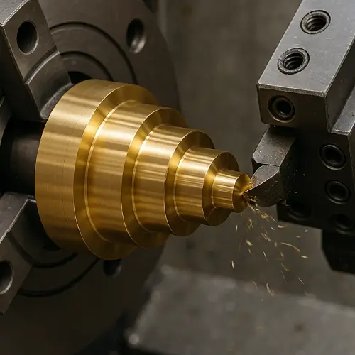
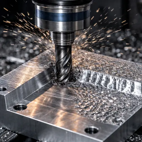
How Clearance Holes Are Machined
Most clearance holes are drilled, and for many jobs that is enough. Standard production parts often use drilling alone when the fit category already provides enough room.
Boring or reaming becomes more useful when the hole needs tighter size control, better roundness, or more repeatable relationship to nearby features.
Hole entry is part of the finished result too. Deburring or light chamfering is often necessary so the fastener enters cleanly. Without that, a correctly sized hole can still behave poorly during assembly.
The process should follow the function. A loose-fit pass-through hole in a non-critical bracket does not need the same attention as a close-fit hole in a more controlled mechanical assembly.
How to Specify a Clearance Hole on a Drawing
A drawing should do more than show a diameter. If fit matters, the design intent should be clear.
The hole size should be defined. The fastener size should be known. If the design depends on close, normal, or loose fit logic, the drawing package should support that choice. If chamfer, deburring, or spotface matters at the same location, those features should be called out clearly rather than left to assumption.
If the hole is only a pass-through feature, that should be obvious. The drawing should not leave room for confusion with a tapped hole or a press-fit feature.
The more assembly-sensitive the hole becomes, the less useful vague callouts become.
Practical Design Tips Before Releasing a Clearance Hole
Do not choose clearance-hole size from bolt diameter alone.
Review whether the bolt is only clamping or also helping align the parts.
Check the full stack, not just one part in isolation.
Allow for coating, plating, paint, or secondary finishing where those are present.
Use close fit only where it adds real value. Use larger clearance when assembly variation is unavoidable.
Do not forget the hole mouth and seating surface. Hardware enters through the edge and loads through the seat, not just through the nominal diameter.
Conclusion
Clearance holes in CNC machining are not just oversized holes for bolts. The right size depends on fit, assembly variation, stack-up, surface condition, and how the joint is meant to go together.
A hole that is technically large enough may still assemble badly if the pattern is off, the entry is rough, the parts are coated, or the seating surface is unstable. That is why clearance-hole design should be treated as an assembly decision, not just a drill-size decision.
If a part includes bolt pass-through holes, stacked plates, coated surfaces, or tighter fit requirements, send the drawing to JeekRapid so hole size, fit, and assembly practicality can be reviewed before production.
FAQs
What is a clearance hole?
A clearance hole is a hole that allows a bolt or screw to pass through without engaging threads in that hole. The clamp load is created elsewhere, such as in a nut or another threaded part.
What is the difference between a close fit and a loose fit clearance hole?
A close fit gives the fastener less room and provides better guidance. A loose fit gives the fastener more room and makes assembly easier when variation, coatings, or stacked parts are involved.
How do I choose the right clearance hole size?
Start with the fastener size, then choose the fit based on assembly needs. Consider whether the hardware is only clamping, whether multiple parts are stacked, whether coatings are present, and how much alignment variation the joint must absorb.
Is a clearance hole the same as a tapped hole?
No. A clearance hole lets the fastener pass through. A tapped hole carries the thread and engages the fastener directly.
Why does a correctly sized clearance hole still cause assembly problems?
Because diameter is only part of the story. Hole position, burrs, chamfer, coating thickness, stack-up, and the local seating surface can all affect how the assembly actually goes together.