Surface Grinding: Process, Tolerances, Finish & Uses
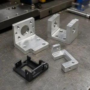
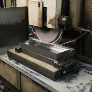
Surface grinding is a precision machining process used to produce flat surfaces, control part thickness, and improve flatness, parallelism, and surface finish. A rotating abrasive wheel removes small amounts of material while the workpiece moves beneath it on a reciprocating or rotary table.
The process is commonly used after CNC milling or heat treatment when …