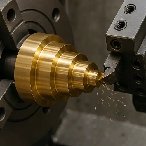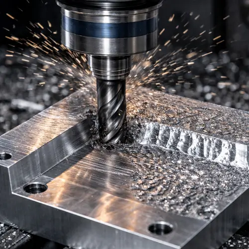
CNC machining depends on more than the machine, program, and material. The cutting tool decides how the material is removed, how clean the feature looks, and how stable the final dimension can be held.
A machined part rarely uses only one cutter. A typical CNC job may start with rough milling, move into drilling, reaming, tapping, boring, chamfering, and finishing. Each tool has a different job. Some remove material quickly. Some control hole size. Some finish surfaces. Some prepare edges for assembly. Some cut threads or grooves that cannot be produced well with a general end mill.
That is why cutting tool selection is part of the machining process, not just a tooling detail. A small aluminum bracket, a stainless steel shaft, a tight-tolerance plastic housing, and a hardened steel insert may all require different CNC cutting tools, even when the drawing looks simple at first.
What Are CNC Cutting Tools?
CNC cutting tools are the tools mounted in CNC mills, lathes, machining centers, turning centers, and multi-axis machines to remove material from a workpiece. The tool may rotate against a fixed workpiece, as in milling and drilling. The workpiece may also rotate against a fixed cutting edge, as in CNC turning.
In CNC milling, common tools include end mills, face mills, drills, reamers, taps, thread mills, ball nose cutters, chamfer tools, countersinks, and counterbores. These tools are held in toolholders and often changed automatically through the machine’s tool magazine.
In CNC turning, cutting tools are usually mounted in a turret. Turning inserts, boring bars, grooving tools, threading inserts, and parting tools are used to machine shafts, bushings, sleeves, pins, threaded parts, and other round components.
The CNC program controls the toolpath, but the cutting tool still has to match the material and feature. Tool diameter, flute length, edge geometry, coating, rigidity, coolant access, feed rate, spindle speed, and tool reach all affect the final result. A correct tool can make a process stable. A poor tool choice can create chatter, heavy burrs, rough finishes, oversized holes, broken taps, or inconsistent dimensions.
Common CNC Cutting Tools Used in Machining
Most CNC machined parts are made with several tools in sequence. One tool may rough out the material. Another may finish the wall. A drill may create a hole. A reamer may bring the hole to size. A tap or thread mill may cut the thread. A chamfer tool may break the edges before inspection.
The table below gives a practical view of common CNC cutting tools and where they are usually used.
| CNC Cutting Tool | Common Use in CNC Machining | Typical Part Features |
|---|---|---|
| End mill | General milling, slotting, pocketing, profiling | Slots, pockets, steps, side walls, contours |
| Face mill | Large flat surface machining | Datum faces, broad flat areas, stock cleanup |
| Drill | Hole making | Clearance holes, pilot holes, blind holes, through holes |
| Reamer | Accurate hole finishing | Dowel holes, pin holes, precision bores |
| Tap | Internal thread cutting | Screw holes, threaded holes, mounting holes |
| Thread mill | Milled internal or external threads | Large threads, blind-hole threads, hard materials |
| Boring bar | Internal diameter finishing | Bearing bores, sleeve holes, concentric features |
| Turning insert | CNC turning operations | Shafts, diameters, faces, tapers, shoulders |
| Grooving tool | Groove cutting | O-ring grooves, snap ring grooves, relief grooves |
| Parting tool | Cut-off operations | Bar stock separation, turned part cutoff |
| Chamfer tool | Edge breaking and chamfering | Assembly edges, hole chamfers, deburred corners |
| Countersink | Conical screw seat machining | Flat-head screw holes |
| Counterbore | Flat-bottom screw seat machining | Socket head screw pockets |
| Ball nose cutter | 3D surface machining | Curved surfaces, molds, contoured geometry |
| Slitting saw | Thin slot cutting | Narrow grooves, side slots, cut-off slots |
| Form cutter | Special profile cutting | Custom radii, undercuts, repeated profile features |
End Mills
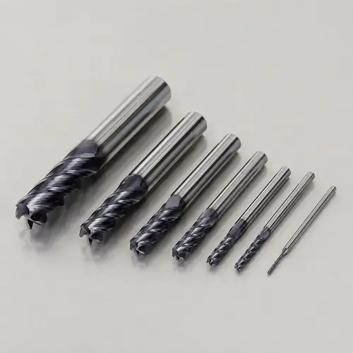
End mills are among the most common cutting tools in CNC milling. They can cut from the end of the tool and along the side of the tool, which makes them useful for many part features. Pockets, slots, side walls, steps, outer profiles, and internal contours are often machined with end mills.
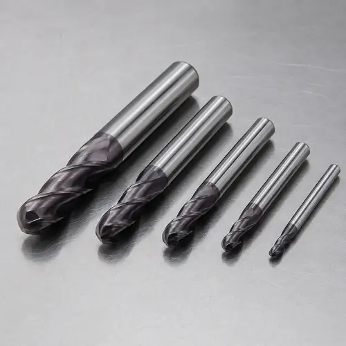
A flat end mill is used when the part needs a flat floor, square shoulder, or straight side wall. This tool is common in pocket machining, step milling, and general profile cutting. A ball nose end mill has a rounded end and is used for curved surfaces, 3D profiles, mold features, and smooth blended geometry. A corner radius end mill, often called a bull nose end mill, has a small radius at the cutting corner. That radius strengthens the edge and helps the tool survive heavier cuts better than a sharp corner tool.
Tool diameter matters. A larger end mill is more rigid and removes material faster, but it cannot machine small internal corners or narrow slots. A smaller end mill reaches tighter geometry, but it is easier to deflect or break. For deep pockets or narrow channels, tool reach becomes a serious issue. A long end mill can reach the feature, but that does not mean the tool can hold the wall straight under cutting pressure.
Flute count also changes performance. Aluminum often needs tools with fewer flutes and larger chip space, because chips must leave the cut quickly. Steel and stainless steel may use tools with more flutes when the setup is rigid and the operation needs better finishing support. Plastic machining often needs sharp cutting edges and good chip evacuation to avoid melting, rubbing, or material push-off.
In real CNC machining, end mills are often split into roughing and finishing roles. A roughing end mill removes most of the material. A finishing end mill takes a lighter pass to improve size, wall quality, and surface finish. This is common when tolerances are tight or the surface is visible.
Face Mills
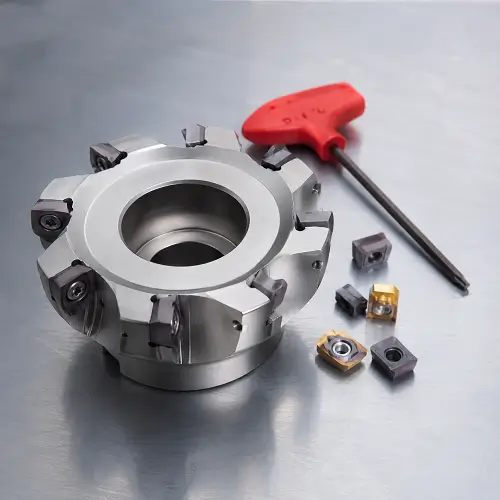
Face mills are used to machine large flat surfaces. Unlike a small end mill, a face mill covers a wide area and usually carries several replaceable inserts around the cutter body. This makes face milling efficient for cleaning up raw stock, squaring a block, machining a datum face, or finishing a large mounting surface.
A flat reference surface is often one of the first important steps in CNC machining. Once a stable datum face is created, the part can be located more reliably for later operations. For housings, plates, brackets, and fixtures, face milling can help establish the surface that other dimensions depend on.
Face mills are productive, but they need a stable setup. A large cutter creates cutting force across a wider area. If the workholding is weak or the machine is not rigid enough for the cut, the result may include vibration, uneven tool marks, poor flatness, or insert wear.
Not every flat surface needs a face mill. Small pockets, narrow ledges, internal steps, and tight areas are usually machined with end mills. Face mills are most useful when the surface is open, broad, and well supported.
Drills and Spotting Tools
Drills are used to make holes in CNC machining. A twist drill is the most common tool for creating round holes, but accurate drilling often starts with a spotting tool. A spot drill creates a small starting point so the drill does not walk across the surface when it enters the material.
Drilling looks simple, but hole quality depends on many details. Hole diameter, hole depth, material hardness, coolant access, drill length, surface angle, and chip evacuation all affect the operation. A short through hole in aluminum is very different from a deep blind hole in stainless steel.
Deep holes are especially sensitive to chip evacuation. If chips pack inside the hole, they can scratch the hole wall, increase heat, damage the cutting edge, or break the drill. Peck drilling, through-coolant drills, and controlled feed rates are often used when hole depth increases.
A drilled hole is not always a precision hole. Drilling may be good enough for clearance holes, pilot holes, and rough preparation. For dowel pins, close-fitting shafts, bearing seats, or alignment holes, drilling is usually followed by reaming, boring, or interpolation.
Reamers
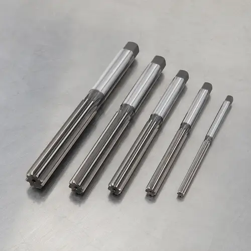
Reamers are used to improve the size accuracy and surface finish of a drilled hole. A drill creates the hole. A reamer brings the hole closer to the final diameter and leaves a cleaner bore wall.
This tool is important when the hole controls assembly. Dowel holes, locating pin holes, slip-fit holes, and precision alignment holes often need reaming. A normal bolt clearance hole may not need that level of control, but a hole used to locate two mating parts usually does.
A reamer does not remove much material. The hole must be drilled slightly undersize before reaming. If too much stock is left, the reamer may overload or cut poorly. If too little stock is left, the reamer may rub instead of cut. Both conditions can hurt hole quality.
Reaming also does not fix a badly located hole. If the drilled hole is already off position, the reamer usually follows the existing hole. For accurate reamed holes, the process before reaming still matters. Spotting, drilling, fixturing, machine alignment, and tool condition all affect the final result.
Taps
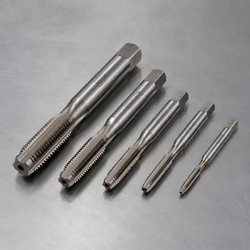
Taps are used to cut internal threads. After a hole is drilled to the correct tap drill size, the tap enters the hole and forms the thread profile. Tapping is common for screw holes, mounting holes, covers, brackets, housings, fixtures, and many mechanical components.
Cutting taps remove material and create chips. Forming taps, also called roll taps, displace material instead of cutting it. Forming taps can produce strong threads in suitable ductile materials, but they require the correct hole size and are not suitable for every material.
Blind holes make tapping more difficult. Chips have less space to escape, and the tap must stop before reaching the bottom. In stainless steel, small thread sizes, hard materials, or deep blind holes, tap breakage is a real risk. A broken tap can be difficult to remove and may scrap the part.
Tapping is fast and cost-effective when the material, hole depth, and thread size are suitable. When the thread is large, the material is hard, or the part is too valuable to risk tap breakage, thread milling may be a safer method.
Thread Mills
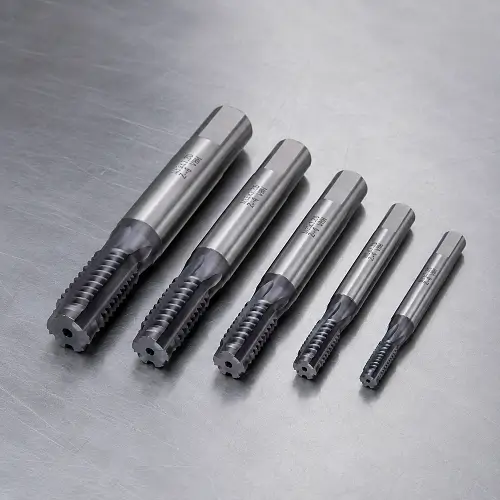
Thread mills cut threads by milling rather than tapping. The tool moves in a helical path and gradually cuts the thread profile. This method is often used for large threads, hard materials, blind holes, expensive parts, or applications where tap breakage would create too much risk.
Thread milling is usually slower than tapping, but it gives the machinist more control. A thread mill can often produce different thread sizes within a certain range by changing the CNC program. Cutting pressure is usually lower than tapping, and chips are easier to manage in many materials.
Blind-hole threads are one of the common reasons to use a thread mill. A tap needs lead-in length and chip space near the bottom of the hole. A thread mill can often cut closer to the bottom, depending on tool design and part geometry.
Thread milling also reduces the risk of losing a part because of a broken tap. If a thread mill breaks, the broken tool is usually easier to remove than a tap locked inside the thread. For prototype machining, low-volume precision work, and expensive materials, that lower risk can matter more than cycle time.
Boring Bars and Boring Heads
Boring tools are used to enlarge and finish existing holes. A drill creates the initial hole, but a boring tool improves the hole’s diameter, roundness, straightness, and alignment. Boring is common for bearing seats, sleeve holes, bushings, precision internal diameters, and coaxial features.
In CNC turning, boring bars are used inside round parts. In CNC milling or machining centers, boring heads or boring tools can be used to finish larger holes. The goal is usually better control than drilling alone can provide.
Boring tools are sensitive to overhang. A long boring bar reaching deep inside a part can deflect, vibrate, or leave chatter marks. The diameter-to-length ratio matters. A short, large-diameter bar is more rigid than a long, small-diameter bar. When a deep bore requires tight tolerance, the process may need several passes, careful tool selection, and stable workholding.
Boring is not always fast, but it is often necessary when the hole has a functional role. A bearing bore, seal bore, sliding fit, or location feature cannot rely on rough drilling alone.
Turning Inserts
Turning inserts are used in CNC lathes and turning centers. In turning, the workpiece rotates while the cutting edge removes material. Turning inserts machine outer diameters, faces, shoulders, tapers, grooves, radii, and threads.
Most modern turning tools use replaceable carbide inserts. The insert shape, nose radius, chipbreaker, grade, and coating are selected according to the material and cutting operation. Roughing inserts are used to remove more material. Finishing inserts are used to improve surface finish and size control.
The nose radius has a strong effect on turning. A larger nose radius can improve surface finish and edge strength, but it also increases cutting pressure. Thin-walled parts, small shafts, and weak setups may deflect under higher cutting pressure. A smaller nose radius reduces pressure and reaches sharper details, but the edge may be weaker.
Turning inserts are used for shafts, pins, bushings, collars, spacers, sleeves, threaded rods, and many round precision parts. On mill-turn machines, turning inserts and milling tools may work together in the same setup to reduce handling and improve feature alignment.
Grooving and Parting Tools
Grooving tools cut narrow grooves into a workpiece. In CNC turning, they are used for O-ring grooves, snap ring grooves, relief grooves, undercuts, and other narrow features. A parting tool is a narrow grooving tool used to cut a finished part away from bar stock.
Grooving tools are often thin, which makes rigidity important. A deep groove with a narrow tool can chatter if the setup is weak or if chips cannot escape. Tool width, groove depth, corner radius, coolant access, and feed direction all affect the result.
Groove dimensions are often functional. An O-ring groove affects sealing. A snap ring groove affects part retention. A relief groove may allow a shoulder, thread, or mating component to seat correctly. These features need more care than their small size suggests.
Parting also requires attention. A poor parting operation can leave a heavy burr, uneven cutoff face, or tool breakage near the end of the cut. For production turning, a stable parting process saves time and reduces secondary finishing.
Chamfer Tools
Chamfer tools are used to break sharp edges and machine angled transitions. A chamfer may help a screw enter a hole, reduce a sharp handling edge, improve assembly, remove a light burr, or prepare a part for finishing.
Chamfering is sometimes treated as a small detail, but it affects how the part feels and assembles. A part can pass major dimensions and still cause trouble if the edges are sharp, burred, or inconsistent. A controlled chamfer makes the part safer to handle and easier to assemble.
Chamfer tools are used around holes, pocket edges, outer profiles, shoulders, slots, and machined faces. Some drawings only require a general edge break. Others specify an exact chamfer size, such as 0.010 in x 45 degrees or 0.020 in x 45 degrees. When the chamfer affects fit or appearance, the requirement should be clear on the drawing.
Countersink and Counterbore Tools
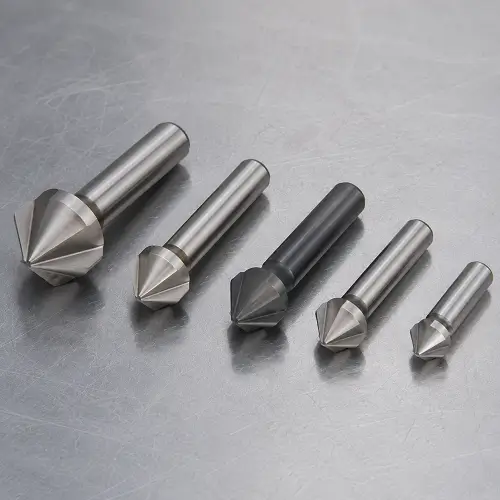
Countersink and counterbore tools prepare holes for fasteners. A countersink creates a conical seat, usually for flat-head screws. A counterbore creates a flat-bottom cylindrical pocket, often for socket head cap screws or bolt heads.
These features are common in plates, covers, brackets, fixtures, enclosures, and assembly components. They look simple, but poor machining can cause screw heads to sit unevenly, chatter marks around the seat, oversized pockets, rough edges, or weak clamping contact.
Countersinks can chatter in some materials because the tool contacts the workpiece across a wide angled surface. A sharp tool, proper speed, controlled feed, and rigid setup help reduce vibration. Counterbores need accurate alignment with the pilot hole so the fastener head sits flat.
Fastener seating matters in assemblies. If the screw head does not sit properly, clamping force may be uneven, the part may distort, or the fastener may not meet the design intent.
Ball Nose Cutters
Ball nose cutters are used for curved surfaces and 3D machining. The rounded tool tip allows the cutter to follow complex shapes without leaving square steps. These tools are common in mold components, aerospace parts, medical components, turbine-style geometry, contoured brackets, and cosmetic surfaces.
Surface finish with a ball nose cutter depends heavily on step-over. A large step-over leaves visible scallop marks. A smaller step-over improves surface quality but increases cycle time. For high-quality 3D surfaces, the finishing pass can take much longer than roughing.
Ball nose cutters are not only for mold work. Any part with blended surfaces, curved pockets, sculpted profiles, or smooth radius transitions may need ball nose machining. In 5-axis CNC machining, tool angle can also be adjusted to improve contact and reduce tool marks.
Slitting Saws, Keyseat Cutters, and Side Cutters
Some features cannot be machined efficiently with a standard end mill. Slitting saws, keyseat cutters, and side cutters are used for thin slots, side grooves, retaining features, and certain undercut-style shapes.
A slitting saw is a thin circular cutter used to produce narrow slots. It can cut slot widths that would be difficult or inefficient with a long, small-diameter end mill. Keyseat cutters can machine side slots, keyway-style features, and certain internal relief areas. Side cutters can reach features from the side of the workpiece.
These tools need careful setup. A thin cutter can deflect, rub, or break if feed rate is too aggressive or if chips get trapped in the cut. Tool runout also matters because a small amount of runout can make the slot wider than expected.
For deep or narrow features, lighter passes, better coolant flow, and stable fixturing are often more important than simply pushing the cutter harder.
Form Cutters and Custom Tools
Form cutters and custom tools are used when a standard cutter cannot produce a feature efficiently. A form tool may machine a special radius, groove, profile, undercut, or repeated production feature in one operation.
Custom tools are not always the first choice. They add tooling cost and may increase lead time. For prototypes or low-volume parts, a shop may prefer to machine the feature with standard tools and a longer toolpath. For repeat production, a custom cutter may reduce cycle time and improve consistency.
The decision depends on geometry, tolerance, quantity, and cost. A custom cutter makes sense when the feature cannot be made reliably with standard tools or when the production volume justifies the tooling investment.
Common Materials Used for CNC Cutting Tools
Cutting tool material affects edge strength, heat resistance, wear resistance, cutting speed, and tool life. The same tool shape can behave very differently depending on whether the tool is made from high-speed steel, carbide, ceramic, CBN, or PCD.
High-Speed Steel
High-speed steel, often called HSS, is a tough tool material used for drills, taps, reamers, and some lower-speed cutting tools. HSS is not as hard or wear-resistant as carbide, but it can handle impact and bending better in certain conditions.
HSS tools are still useful for manual work, repair machining, tapping, and some hole-making operations. They also cost less than carbide tools. In modern CNC milling, HSS is less common for high-speed production because carbide usually runs faster and holds the cutting edge longer.
Carbide
Carbide is one of the most widely used tool materials in CNC machining. Solid carbide end mills, carbide drills, and indexable carbide inserts are common in shops that machine aluminum, steel, stainless steel, titanium, copper, brass, and engineering plastics.
Carbide is harder and more wear-resistant than HSS. It supports higher cutting speeds and longer tool life when the machine, holder, and workholding are rigid. The tradeoff is brittleness. Carbide does not tolerate heavy vibration, poor clamping, or sudden impact as well as tougher tool materials.
For many CNC parts, carbide offers the best balance between productivity, accuracy, and tool life. This is why carbide end mills and carbide inserts are common in both prototype machining and production machining.
Ceramic Tools
Ceramic cutting tools are used in high-temperature and high-speed applications, such as machining hardened materials or cast iron. Ceramic tools handle heat very well, but they are brittle compared with carbide and HSS.
A ceramic insert needs stable cutting conditions. Heavy interruption, weak fixturing, or vibration can chip the edge. These tools are not usually selected for general-purpose machining. They are used when the material, machine, and cutting condition are suitable.
CBN Tools
CBN stands for cubic boron nitride. CBN tools are used for hard turning, hardened steels, and high-wear applications. They are much more expensive than standard carbide tools, but they can perform well where carbide wears too quickly.
CBN tools require a rigid machine, stable setup, and correct cutting parameters. They are not used casually. When applied correctly, CBN tooling can reduce grinding work or improve productivity on hardened components.
PCD and Diamond-Coated Tools
PCD means polycrystalline diamond. PCD and diamond-coated tools are used for non-ferrous and abrasive materials such as aluminum, copper, brass, graphite, carbon fiber composites, and some abrasive plastics.
Diamond tools can provide excellent wear resistance and surface finish in the right materials. They are not normally used for ordinary steels because diamond is not suitable for iron-based materials at high cutting temperatures.
For aluminum parts with high finish requirements or abrasive composite materials, PCD tools can be a strong choice. The cost is higher, so the decision usually depends on material behavior, production quantity, tool life expectations, and finish requirements.
Tool Geometry and Coatings in CNC Cutting Tools
Tool material is important, but geometry often decides how the tool actually cuts. Two carbide end mills can perform very differently if the flute count, helix angle, rake angle, relief angle, edge preparation, or corner radius is different.
A tool for aluminum usually needs sharp cutting edges and enough flute space to move chips out quickly. A tool for stainless steel needs edge strength, heat resistance, and a geometry that helps control work hardening. A tool for plastic needs sharp edges and clean chip formation so the material does not melt, smear, or deflect away from the cutter.
Flute count is one common example. A two-flute or three-flute end mill may work well in aluminum because chip clearance is important. A four-flute or higher-flute tool may work better in steel finishing when the setup is rigid. There is no single best flute count for every material.
Corner radius also matters. A sharp corner can cut fine details, but the edge is weaker. A small corner radius strengthens the tool and can improve tool life. The tradeoff is that the tool radius affects the internal corner left on the part. Sharp internal corners are difficult in CNC machining because the cutter always has a physical radius.
Coatings are used to improve wear resistance, heat resistance, lubricity, or chip flow. Common coating types include TiN, TiAlN, AlTiN, DLC, and diamond coatings. The right coating depends on the workpiece material. A coating that works well in steel may not be the best choice for aluminum. A coating that helps with abrasive composites may not make sense for soft plastics.
Tool geometry and coating should be selected together with cutting parameters. A good cutter can still fail if the speed, feed, coolant, toolholder, or workholding is wrong.
How to Choose the Right CNC Cutting Tool for a Machined Part
Choosing a CNC cutting tool starts with the part, not the tool catalog. The machinist looks at the material, feature shape, tolerance, surface finish, tool reach, machine type, and production quantity before deciding how to cut the part.
Part Material
Material is one of the first decisions. Aluminum usually needs sharp tools and strong chip evacuation. Stainless steel needs heat control, edge strength, and cutting conditions that avoid work hardening. Titanium needs careful heat management and stable cutting pressure. Plastics need sharp edges and a process that avoids melting, cracking, or distortion.
The same end mill is not ideal for all of these materials. A tool that runs well in aluminum may load up or wear quickly in stainless steel. A tool that works in steel may create too much heat or pressure in plastic.
Machined Feature
The feature shape decides the tool type. A flat pocket may need an end mill. A large face may need a face mill. A tight bore may need drilling and reaming, or drilling and boring. A threaded hole may need tapping or thread milling. A screw seat may need a countersink or counterbore. A narrow groove may need a grooving tool, keyseat cutter, or slitting saw.
Good tool selection starts by asking what the feature must do. A simple clearance hole does not need the same process as a precision dowel hole. A cosmetic chamfer does not need the same control as a sealing surface. A tapped hole in aluminum is not the same risk as a blind M3 thread in stainless steel.
Tolerance and Surface Finish
Tight tolerances often require separate roughing and finishing tools. Roughing removes material quickly. Finishing removes a smaller amount of stock with lower cutting pressure. This helps control size, straightness, and surface quality.
Surface finish also changes tool choice. A visible surface may need a dedicated finishing pass, smaller step-over, sharper tool, or better toolpath strategy. A functional bore may need reaming or boring instead of drilling alone. A sealing surface may need more control than a hidden pocket wall.
Tool Reach and Rigidity
Tool reach is a common limit in CNC machining. A deep pocket, tall wall, or recessed feature may require a long tool. Long tools are less rigid and more likely to deflect or chatter.
The best tool is usually the shortest tool that can safely reach the feature. If a long tool is required, the process may need lighter cuts, better fixturing, different toolpaths, or roughing and finishing in stages.
Toolholder rigidity also matters. A good cutting tool can still produce poor results if the holder has runout or the setup allows vibration.
Prototype or Production Quantity
Prototype machining and production machining often use different tooling decisions. For one or two parts, a shop may use standard tools and accept a longer cycle time. For repeat production, a custom tool or optimized insert may reduce cycle time and improve consistency.
Quantity also affects risk. A process that works once may not be stable across 500 parts. Production machining needs tool life, repeatability, and inspection control. The tool must cut the first part correctly and still hold the process after many cycles.
How JeekRapid Plans CNC Tooling Before Machining
JeekRapid reviews the CAD file, drawing notes, material, tolerance requirements, surface finish callouts, hole depth, wall thickness, thread type, and batch quantity before selecting CNC cutting tools. Tool selection is planned together with workholding, toolpath strategy, machine selection, coolant use, and inspection method.
A prototype aluminum housing, a stainless steel shaft, and a PEEK precision component may all need different cutters and cutting strategies. Aluminum may need sharp carbide tools with good chip evacuation. Stainless steel may need coated carbide tools, controlled cutting heat, and careful tapping or thread milling. Plastics may need sharp geometry and lighter cutting pressure to avoid deformation.
JeekRapid does not treat cutting tools as a separate detail from the machining process. The tool must match the part requirement. Deep holes, tight bores, thin walls, internal threads, narrow slots, and strict surface finish requirements all need proper planning before machining starts.
For custom CNC machined parts, this tooling review helps reduce chatter, burrs, dimensional drift, rough finishes, broken tools, and unexpected rework.
Conclusion
CNC cutting tools are selected according to the part, not just by tool name. End mills, face mills, drills, reamers, taps, thread mills, boring bars, turning inserts, grooving tools, chamfer tools, countersinks, counterbores, ball nose cutters, and specialty cutters all serve different machining purposes.
A stable CNC machining process depends on matching the cutter type, tool material, tool geometry, coating, workholding, cutting parameters, coolant strategy, and inspection method to the part requirement. When these decisions are made correctly, the part is more likely to hold tolerance, finish cleanly, assemble properly, and repeat consistently.
JeekRapid can review CAD files and technical drawings before machining to help identify a suitable CNC process, tooling approach, material option, and inspection plan for custom machined parts. Upload your CAD files to request a CNC machining quote.