Hole position in CNC machining becomes a real problem when the parts reach the bench and have to go together without forcing, slotting, or reworking anything. On paper, the holes may look fine. The inspection sheet may show acceptable sizes. The machined surface may even look clean and well finished. Then assembly starts, and the trouble shows up fast. Three bolts start, the fourth does not. One dowel pin enters, the second stops halfway. A cover looks like it should drop into place, but someone has to tap it, twist it, or push it just to make it sit.
That kind of problem usually has very little to do with how the hole looks by itself. The real issue is that the hole center, or the full pattern, is not sitting where the mating part expects it to be. When the part depends on repeatable alignment, diameter alone does not decide whether the part is good. Hole location does.
Why do CNC holes fail in assembly even when the size is correct?
People usually look at diameter first because diameter is easy to read, easy to inspect, and easy to talk about. If the print calls for a 6.00 mm hole and the report shows 6.01 mm, most people relax. The hole looks fine, so the assumption is that the feature is fine. That assumption falls apart the moment the pattern has to match something else.
A bolt does not care much about the report if the hole center is shifted. A dowel pin does not care that the hole is smooth if the pattern is slightly rotated. What matters in the real assembly is whether the holes land in the usable location, not whether each one looks acceptable by itself.
This shows up all the time on covers, brackets, manifolds, flanges, mounting plates, and pinned components. A loose clearance hole may survive a little error because the fastener still finds its way through. A locating feature does not behave like that. Once the center moves, the whole relationship between the parts moves with it.
That is why a part can pass a basic inspection and still create an argument in assembly. The size may be right. The pattern is not where it needs to be.
Why do bolt holes or dowel holes not line up?
Most of the time, nothing looks wildly wrong. The holes are there. The finish is decent. The spacing looks close enough by eye. Then the mating part comes over, and suddenly the pattern feels tight, one side starts before the other, or the parts only line up after someone nudges them around by hand.
Small position errors stack up quietly. One hole sits a little high. Another drifts a little toward the edge. A third is just slightly rotated around the pattern center. None of those errors seems dramatic on its own. Put them together across a bolt circle or a locating pair, and the fit changes completely.
Bolt holes sometimes hide the problem because clearance gives you some room. Operators can wiggle the part, pull it with the bolts, or chase the fit enough to make it work. Dowel holes expose the problem immediately. A dowel hole is not there to forgive error. It is there to define where the part sits. Once the center is off, the pin tells the truth very quickly.
That is why parts can look nearly identical on the table and still refuse to fit together. Visual similarity means very little when the pattern is doing real locating work.
What causes hole position error in CNC machining?
Most hole-position trouble does not come from one dramatic mistake. It usually comes from ordinary shop-floor issues that build on each other until the pattern drifts far enough to matter.
Workholding is one of the first places to look. A thin plate can pull slightly under clamping load. A long bracket can relax after one side is machined. A part that feels stable in the vise can still move just enough during drilling to shift a hole center. That kind of movement rarely announces itself. The hole still gets cut. The problem only appears later when the part meets the mating component.
Multiple setups are another common source of trouble. Once a part is unclamped, flipped, or picked up again, the process depends on how well the new setup reproduces the original relationship. Even in a good shop, that is not as clean as keeping a critical pattern in one setup. A plate machined from one side and then indicated again from an edge or face on the second setup may come out looking fine, but the hole group can move just enough to create assembly issues.
Drill behavior matters more than many buyers realize. A drill is not a magic locator. If the spot is weak, the entry surface is uneven, the tool stick-out is longer than it should be, or the material pushes the tool off course, the drill will follow its own path. That shift may only be a few hundredths of a millimeter or a few thousandths of an inch, but on a dowel pair or a tight pattern, that is already enough to change how the part fits.
Then there are the quieter shop-floor problems. Tool deflection, spindle runout, worn holders, probing error, backlash, heat buildup, part stress release, and machine calibration drift do not always show up clearly on a loose-tolerance job. Put the same machine on an alignment-critical part, and suddenly the small habits in the process start to matter.
Can reaming fix hole position problems?
A lot of people hope it can. In practice, it usually cannot.
Reaming is good at what it is meant to do. It improves size consistency, finish, and fit when the starting hole is already in the right place. What it does not do well is move a misplaced hole back to where it should have been from the start.
Once the drill has established the path, the reamer normally follows that path. The finished hole may feel cleaner. The pin may feel smoother. The size may come into tolerance more consistently. But if the original center was wrong, the finished center is usually still wrong.
This is one of those issues that shows up late and frustrates everyone. The shop may say the hole was drilled and reamed correctly. The assembly technician may still be fighting the fit. Both can be telling the truth. The hole quality improved, but the pattern never recovered its intended location.
When the real risk is position, the answer has to come earlier in the process. Better datum control, better setup strategy, and a better method for producing the feature matter more than trying to rescue the result afterward.
Which hole-making method gives better position accuracy?
Not every hole should be treated the same way, even if the drawing shows them with similar diameters. Shops often group holes together because it saves time in programming and cycle time on the machine. The assembly does not care about programming convenience. It only cares which holes actually control the fit.
A simple drilled hole is usually the right choice for general mounting and clearance work. It is fast, economical, and perfectly reasonable for many parts. Trouble starts when the same logic gets applied to holes that are actually locating features.
Reaming has its place, especially when the hole needs better size control or a better fit with a pin. The limitation is that reaming depends on the starting hole already being where it should be. It refines the feature. It does not reposition it.
Boring is slower, but it gives the process more control over the final center and geometry. That is why it is often chosen for locating bores and alignment-critical holes. Circular interpolation can also be a good option on a stable CNC setup. In the right part and the right material, it gives more controlled geometry than simply pushing a drill through.
The process should match the job the hole is doing. A clearance hole only needs enough positional control to let the hardware pass and clamp properly. A dowel hole is doing something more serious. It is deciding where the part sits. Treat those two holes the same way, and the easy feature gets extra attention while the critical one does not get enough.
Why do some parts pass inspection but still fail on the assembly bench?
A shop may verify diameter, edge distance, and a few point-to-point dimensions. The report may look calm. Then the part goes to assembly, and the pattern no longer matches the mating component. The mechanic or technician does not care that the measured values look reasonable. The part still will not go together cleanly.
This happens when the inspection is focused on individual values while the assembly is relying on the relationship between features. A hole pattern is not judged one hole at a time in real use. It is judged as a group. The spacing, the orientation, the center locations relative to the functional datums, and sometimes the relationship to a bore or a mounting face all matter at the same time.
On less critical work, that difference may never become visible. On tighter assemblies, it shows up immediately. A flange rocks. A plate needs prying to start the bolts. A gauge plate refuses to sit flat. An operator reaches for a round file, and everyone pretends the problem is minor.
That is why critical parts often need something more meaningful than a quick size check. CMM data, datum-based probing, fixture checks, or even a controlled fit check with the mating part can tell the truth much faster than a clean-looking dimension sheet.
Are drawing mistakes causing the hole problem?
Some drawings look complete because the dimensions are all there, but the real functional intent is still unclear. Hole diameter may be called out correctly while the part never clearly states which holes are doing the locating and which holes are only giving the fasteners room to pass.
Datum choice is another common problem. Outside edges are convenient for dimensioning, so they end up on a lot of prints. The assembly may not care about those edges at all. It may locate from a machined face, a shoulder, a bore, or a register. If the print is built around one reference scheme and the product works from another, the shop can follow the print and still produce a part that behaves badly on the bench.
There is also a big difference between clearance holes and locating holes, and many drawings blur that distinction. A clearance hole just needs enough freedom to let the hardware do its job. A locating hole defines where the part sits. When both are treated the same way, money gets spent in the wrong places and the real risk stays hidden until assembly.
Coordinate dimensions can also be misleading when they describe a pattern without making the pattern’s function clear. The drawing may look tidy, but the shop is left guessing what matters most if something has to be held tighter than the rest.
Which holes need tighter position control?
The answer starts with function, not with diameter.
A standard clearance hole often has some room to live with small shifts. The bolt still passes through, the clamp load pulls the parts together, and the assembly works well enough. That is why not every mounting hole needs the same level of positional attention.
The situation changes the moment the hole begins to define the part’s location. Dowel holes, pilot holes, alignment holes, locating patterns, and features that must match another custom component usually need much tighter control because those holes decide where the final assembly ends up.
A simple way to think about it is this: some holes allow the assembly to happen, while others decide how the assembly sits. The second group is where position matters most. Those are the holes worth discussing early, machining carefully, and inspecting in a way that matches real use.
What should be reviewed before sending a hole-critical part for CNC machining?
It helps to look at the drawing like the person who will have to put the parts together later.
Which holes are only there for bolts? Which holes actually locate the part? Which pattern has to match another machined component without hand adjustment? Can the critical group be cut in one setup, or is the current process already forcing a re-clamp that adds risk? Are the datums on the print tied to the real assembly, or are they just convenient drafting references?
Those questions are worth answering before the first part is cut. Once the wrong relationship is machined into a batch, the usual fixes are ugly. Holes get opened up. Patterns get slotted. People force parts together and hope clamp load hides the problem. Sometimes the parts simply become scrap.
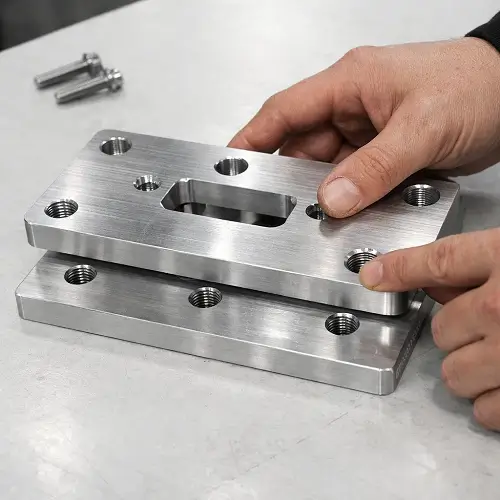
On assemblies with tighter hole relationships, it often makes more sense to review both mating parts together. Looking at one print in isolation can miss the exact condition that later shows up in the fit.
How JeekRapid handles hole-location-critical CNC parts
When a job depends on hole position, JeekRapid does not treat every hole as if it carries the same level of risk. Clearance holes, dowel holes, and locating patterns are doing different work in the assembly, so the machining plan should reflect that from the start.
The first question is always functional. If the pattern controls how the part sits against another part, then datum logic, setup sequence, and hole-making method all need to support that requirement before production begins. It is much cheaper to sort that out early than to discover the issue later when the holes already exist and the pattern is fighting the assembly.
That is also why hole-critical parts are reviewed with the full fit in mind, not just the isolated feature. A clean, round hole is easy to produce. A hole pattern that drops into place on the bench without drama is what the customer was actually paying for.
Conclusion
Hole position problems are easy to hide behind acceptable hole size. The part looks fine, the holes look clean, and the report does not seem alarming. Then assembly starts, and the real condition shows up.
On hole-critical CNC parts, the question is not only whether the hole was machined cleanly. The real question is whether the pattern lands where the mating part needs it to land. If your part includes critical hole diameters, bolt patterns, dowel holes, or locating holes, send your drawing to JeekRapid before machining begins. A quick review at that stage can catch hole-location risks early and reduce the chance of rework, fit problems, or scrap later.
FAQ
Can a hole be within size tolerance and still cause assembly trouble?
Yes. The diameter may be acceptable while the center location is still far enough off to affect how the parts line up.
Why do bolt holes sometimes look fine but still not line up?
Because the pattern works as a group. Small shifts across several holes add up faster than most people expect.
Will reaming fix a hole that started in the wrong place?
Usually not. Reaming improves size and finish much more reliably than it corrects location.
Which CNC holes are most sensitive to position error?
Dowel holes, locating holes, alignment features, and any pattern that defines how one part sits against another.
Should both mating parts be reviewed together before machining?
On alignment-critical work, yes. Many fit problems only become obvious when both parts are looked at as one functional pair.