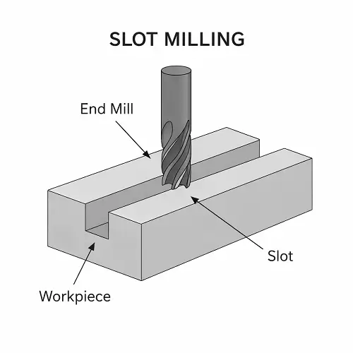
Slot milling is a CNC milling operation used to cut straight or curved slots, grooves, and channels into a workpiece. Depending on the slot shape and access, the operation may use an end mill, slot drill, side milling cutter, T-slot cutter, or another form tool.
A wide, shallow slot in aluminum may be straightforward. A narrow slot with greater depth, tight width tolerance, or restricted chip clearance can be one of the more difficult features on the same part. Tool diameter, cutting depth, slot length, material, corner geometry, and tolerance all affect whether the slot can be machined efficiently and held consistently.
What Is Slot Milling?
Slot milling removes material along a defined path to create a channel with a controlled width and depth. Slots are common in brackets, fixture plates, housings, machine components, keyways, sealing features, adjustment mechanisms, and assemblies that need clearance for another part.
The cutter normally rotates while the CNC machine moves it along the programmed slot path. In a simple full-width cut, the tool engages both side walls at the same time. For wider or more accurate slots, the machine may rough the center first and then finish each wall separately. This reduces cutting load and gives the machinist more control over final width, straightness, and surface finish.
Slot milling is sometimes called CNC slotting, slotting milling, groove milling, or milling a slot. These terms can overlap, although “grooving” is broader and can also describe operations performed on a lathe.
How Does Slot Milling Work?
The process starts with the slot geometry on the CAD model and drawing. The programmer selects a cutter that can enter the feature, reach the required depth, and leave the specified internal radius. The toolpath is then planned around the slot width, whether the ends are open or closed, the material, and the amount of stock that should remain for finishing.
A shallow slot may be cut with one or several axial passes. Deeper slots are normally machined in steps so chips can leave the cut and the tool is not loaded across its full flute length at once. When the final width matters, roughing usually leaves a small, controlled amount of material on both walls. Separate finishing passes then bring the slot to size.
Closed slots require a way for the cutter to enter the material. The tool may ramp into the slot, follow a helical entry where space allows, or enter through a predrilled hole. Plunging straight down with an end mill is only suitable when the tool is designed for center cutting and the cutting conditions allow it.
Coolant or compressed air helps remove chips from the channel. This becomes increasingly important as the slot gets deeper because trapped chips can be recut between the tool and walls, increasing heat and damaging the finish.
Common Types of Slot Milling
Different slot shapes require different cutters and tool access. The table below shows the most common forms found on CNC machined parts.
| Slot type | Typical cutter or method | Common use |
|---|---|---|
| Straight open slot | End mill, slot drill, or side milling cutter | Adjustment slots, guides, brackets, and clearance features |
| Closed slot | Center-cutting end mill with ramp, helix, or predrilled entry | Housings, pockets with narrow channels, and internal locating features |
| Keyway or keyseat | End mill, keyseat cutter, or Woodruff cutter | Shafts, hubs, gears, and power-transmission components |
| T-slot | End mill for the neck followed by a T-slot cutter | Machine tables, fixtures, clamps, and sliding attachments |
| Dovetail slot | Dovetail cutter after an access path is opened | Slides, guides, and mechanical locking features |
| Curved or profile slot | End mill following a programmed contour | Adjustment paths, cam features, and custom guides |
These operations all produce slot-like features, but they do not create the same machining conditions. A straight open slot gives chips an easier escape path. A closed slot traps the cutter between walls. T-slots and dovetails require an initial access channel before the form cutter can machine the undercut.
What Cutters Are Used for Slot Milling?
Solid carbide end mills are widely used for straight and curved CNC slots because they are rigid, accurate, and available in many diameters and flute lengths. A cutter close to the finished slot width can produce the feature directly, but it leaves little room to adjust wall position. Using a smaller cutter and finishing the two walls separately often provides better control when the width tolerance is important.
Flute count should match the material and chip space. Two- or three-flute tools are common for aluminum because the larger flute valleys give chips more room to escape. Four-flute or other multi-flute tools may suit steel when tool rigidity and cutting-edge engagement are more important. Stainless steel needs a sharp, stable cutter and cutting conditions that avoid rubbing and local work hardening.
Side-and-face cutters can machine open slots efficiently when the machine setup provides access from the side. T-slot cutters, Woodruff cutters, and dovetail cutters are form tools used for specific profiles rather than general straight slotting.
Tool diameter is only part of the decision. The cutter must also have enough flute length and neck clearance to reach the bottom without rubbing its shank against the walls. Extra tool length reduces rigidity, so the shortest practical cutter and holder arrangement is normally preferred.
Slot Milling vs Pocket Milling and Grooving
A slot is usually narrower and more restrictive than a pocket. During full-width slotting, the cutter engages material across most of its diameter and is confined between two walls. A pocket gives the programmer more room to control radial engagement, clear chips, and approach the final boundary from different directions.
This is why a small slot is not automatically easier than a large pocket. The slot can create higher engagement, less chip space, and more sensitivity to cutter movement even though less total material is removed.
Grooving is a broader term. A milled groove may be functionally the same as a slot, while turning grooves are cut on rotating cylindrical parts with a different machine and tool. On a CNC milling machine, the drawing geometry and required cutter path are more useful than the name alone.
How Do Slot Width and Depth Affect Milling?
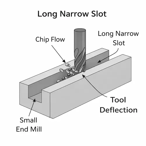
Slot width controls the maximum cutter diameter that can enter the feature. A wider cutter is generally more rigid, while a narrow slot forces the use of a smaller tool. If the slot also needs significant depth, the cutter must combine a small diameter with longer reach—the condition most likely to cause deflection and vibration.
As a practical guide, a slot depth around one to two times the cutter diameter is often manageable with a stable setup and suitable material. At approximately three times diameter, tool reach, chip evacuation, and finishing strategy need more attention. When a narrow slot approaches four or five times cutter diameter, it should be reviewed as a higher-risk feature rather than treated as routine full-width milling.
These are not universal capability limits. A rigid machine, suitable tool, effective coolant delivery, and machinable material can extend the practical range. Tough materials, tight tolerances, limited access, or a flexible workpiece can make the same ratio difficult much earlier.
Slot length affects straightness and wall consistency. A long toolpath gives deflection, heat, and tool wear more opportunity to change the cut. A slot may measure correctly near one end while showing taper, wall drift, or different surface texture farther along its length.
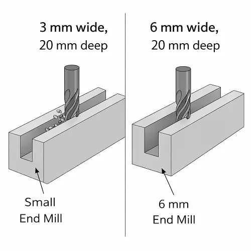
The relationship between the dimensions matters more than any one number. A 3 mm-wide slot that is 20 mm deep requires a small, long-reach cutter and is highly sensitive to chip packing and tool movement. A 6 mm-wide slot at the same depth allows a much more rigid tool and is usually easier to control, even though both drawings show a depth of 20 mm.
Why Are Deep and Narrow Slots Difficult to Mill?
Tool deflection is one of the main limits. A small cutter with long reach bends slightly under cutting force. Even a small amount of movement can change slot width, wall straightness, and the difference between the top and bottom of the feature. The programmed path may be correct while the cutting edge is no longer following it exactly.
Chip evacuation is the next problem. Chips have limited space to leave a deep slot. If they remain around the cutter, they are cut again, hold heat inside the feature, scratch the walls, and increase the chance of tool damage. Aluminum may smear or form built-up edge, while steel and stainless steel place more thermal and mechanical load on the tool.
Full-width engagement also produces more heat than a lighter side-milling cut. When heat, chip recutting, and long tool reach occur together, the slot can begin to drift before there is any obvious tool failure.
Vibration often appears as waviness or repeated marks on one or both slot walls. Excessive holder length, weak workholding, unsupported thin material, or unsuitable cutting parameters can all contribute. Once chatter begins inside a narrow channel, a final pass may not fully remove the damage unless enough stock remains.
Slot Milling Aluminum, Steel, and Stainless Steel
Aluminum normally allows higher cutting speeds and lower cutting forces, but it produces relatively large chips that can pack into a narrow channel. A sharp tool, adequate flute space, and strong chip evacuation help prevent smeared walls, built-up edge, and a streaked bottom finish.
Carbon and alloy steels usually increase tool load and make deflection more noticeable. The process may need smaller step-downs, more controlled entry, and separate finishing passes. Tool wear should be considered when a long slot must remain consistent from one end to the other.
Stainless steel is less forgiving because it retains heat and can work harden when the cutter rubs instead of cutting cleanly. A marginal toolpath can become progressively worse as the material near the slot wall hardens. Stable engagement, suitable tooling, and reliable coolant delivery are especially important on deep stainless steel slots.
Engineering plastics create different risks. Cutting forces may be lower, but heat can soften the material and thin walls can move after machining. Burrs, dimensional recovery, and workholding pressure may affect the final slot more than cutter wear does.
What Problems Occur During Slot Milling?
A slot that is narrower at the bottom than at the top often indicates tool deflection. The cutter bends under load and removes less material deeper in the feature. The same effect can produce tapered walls even when the toolpath has parallel sides.
Different finishes on the two walls usually point to unequal cutting conditions. One wall may be cut during conventional engagement and the other during climb engagement, or the cutter may be pushed more heavily toward one side. Leaving controlled stock and finishing each wall separately can improve consistency.
A rough or streaked slot bottom often begins as a chip problem. Recut chips and trapped heat mark the floor as the cutter passes over them. Stronger evacuation or shallower cutting steps may solve the underlying problem more effectively than adding another light pass at the end.
Heavy exit burrs can indicate unstable tool exit, an unsuitable feed condition, or insufficient support in a thin section. Burrs matter when the slot is part of a sliding, locating, or assembly feature because they can change the effective width and interfere with mating parts.
Dimensional variation can also come from an unrealistic tolerance. Slot width is affected by cutter runout, tool wear, deflection, temperature, material movement, and measurement method. Tightening the drawing tolerance without a functional reason increases machining and inspection effort but does not automatically improve the part.
CNC Slot Design Guidelines for Easier Machining
Use the widest slot that the part function allows. Even a modest increase in width may permit a larger, more rigid cutter and reduce both machining time and dimensional risk. Slot depth should be limited to what the assembly actually needs; unnecessary depth adds reach, chip, and inspection problems without improving function.
Internal radii should match feasible cutter geometry. A standard end mill naturally leaves radiused ends and internal transitions. Calling for sharp internal corners may require EDM, broaching, or another secondary process. If a mating component has square corners, adding corner relief or a dog-bone feature may be more economical than forcing the entire slot to use a very small cutter.
The drawing should specify slot width, depth, length, end geometry, position, and any truly functional surface requirement. Avoid applying the tightest tolerance to every wall and the bottom by default. If only the width controls a sliding fit, the bottom surface may not need the same level of control.
Open-ended slots are generally easier to enter and clear than fully enclosed slots. When design freedom allows, giving the cutter an open exit can improve chip removal and reduce the need for special entry moves.
For tight slot tolerances, state the inspection requirement clearly. A long narrow slot may need width checks at several positions rather than a single measurement near the opening. Related positional and profile requirements should also match how the slot functions in the final assembly. More information about practical tolerance selection is available in our CNC machining tolerances guide.
When Should EDM Be Used Instead of Slot Milling?
Milling is normally the faster and more economical choice for accessible slots with realistic radii. EDM becomes worth reviewing when the feature is extremely narrow and deep, the material is already hardened, or the design requires internal geometry that a rotating cutter cannot reach reliably.
Wire EDM can produce narrow through-slots when the geometry is open through the part and a start hole or edge access is available. Sinker EDM may be considered for blind features or shaped cavities. These processes remove material differently from conventional milling and can produce sharper internal conditions, but they also add time and cost.
The decision should be based on repeatable production, not whether a milling cutter can physically enter the feature once. A slot that requires fragile tooling, very slow cutting, and frequent correction may be more suitable for EDM even if conventional machining is technically possible.
Conclusion
CNC slot milling is used to produce straight, curved, open, closed, and formed channels in metal and plastic parts. The process may use end mills, slot drills, side cutters, or dedicated form tools depending on the slot profile and access.
Simple slots are economical to machine, but difficulty rises when a narrow width is combined with greater depth, long tool reach, tight tolerance, or difficult material. Tool rigidity, chip evacuation, heat, finishing stock, and internal corner requirements should therefore be reviewed together.
JeekRapid provides CNC milling services for prototypes and production parts with slots, pockets, holes, and other precision features. If your drawing includes deep slots, narrow channels, T-slots, keyways, or tightly controlled slot widths, upload your CAD model and 2D drawing for a machining review.