On real CNC jobs,CNC Machining tolerances show up when parts stop fitting, when inspection starts rejecting pieces that look “fine,” or when cost suddenly jumps for no obvious reason. Most of the time, the root cause is the same: tolerances were chosen without thinking through how the part will actually be machined and measured.
If you have ever reviewed a drawing and wondered whether some dimensions feel tighter than they need to be, you are already asking the right question.
What Are CNC Machining Tolerances?
A machining tolerance defines how much a dimension is allowed to vary and still perform its intended function. No machining process produces identical parts. Tolerance simply sets the acceptable window of variation.
In CNC machining, tighter tolerances do not just improve precision. They also increase machining time, tooling wear, inspection effort, and scrap risk. The goal is not to chase the smallest number on the drawing. The goal is to choose tolerances that the process can hold consistently while keeping cost and risk under control.
Typical CNC Machining Tolerances
Standard tolerance
±0.004 in is stable, economical, and repeatable on modern CNC machines for most aluminum and steel parts.
Moderate precision
Around ±0.002 in. This range is common for parts that need controlled fit while still allowing efficient machining and inspection.
High precision
±0.0004 in begins to narrow the process window. Tool condition, temperature control, and setup quality become far more sensitive at this level.
Ultra-precision features
±0.0002 in and tighter are achievable only on specific features under tightly controlled conditions. Production speed slows, inspection increases, and scrap risk rises sharply.
When tolerances tighten, cost does not rise gradually. It climbs quickly. Tool wear increases, cutting speeds drop, inspection time expands, and the chance of scrap grows. In many projects, the difference between ±0.004 in and ±0.001 in is the difference between a smooth production run and a difficult one.
If a feature does not truly depend on extreme precision for function or safety, relaxing that tolerance even slightly can dramatically improve yield and delivery time. This becomes even more important in thin wall CNC machining, where part stiffness and fixturing stability directly affect dimensional control.Many design teams discover this only after the first prototype cycle.
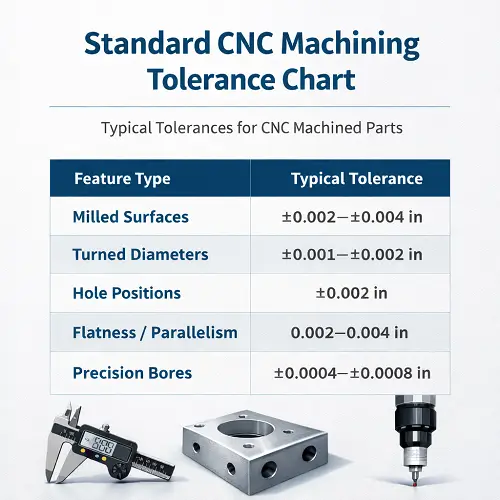
Standard CNC Machining Tolerance Chart
| Feature Type | Typical Tolerance |
|---|---|
| Milled surfaces | ±0.002–±0.004 in |
| Turned diameters | ±0.001–±0.002 in |
| Hole positions | ±0.002 in |
| Flatness / Parallelism | 0.002–0.004 in |
| Precision bores | ±0.0004–±0.0008 in |
Types of Machining Tolerances (What You Actually See on Drawings)
Bilateral tolerance
On most drawings, bilateral tolerance is the default. A dimension such as 10.00 ± 0.05 mm allows equal variation in both directions. It is used for non-critical features and general mating surfaces where small size changes do not affect function.
Unilateral tolerance
Unilateral tolerance restricts variation to one direction, such as 10.00 +0.05 / −0.00 mm. This is used when material must never be removed beyond a functional limit, common for bearing seats, press fits, sealing grooves, and load-bearing interfaces.
Limit tolerances
With limit tolerances, the drawing shows the acceptable range directly, for example 9.95 – 10.05 mm. This removes interpretation and makes machining and inspection straightforward. It is widely used for shafts, holes, and precision fits.
Geometric Tolerances (GD&T) Symbol Quick Reference Chart
When the shape of a part matters more than its size, GD&T symbols are used to control geometry and functional relationships between features.
| Category | Symbol | Name | Typical Application |
|---|---|---|---|
| Form | ○ / ⏤ | Circularity / Straightness | Ensuring smooth rotation of shafts, preventing long components from bending |
| Orientation | ⊥ / // | Perpendicularity / Parallelism | Keeping bases and side walls square to prevent assembly misalignment |
| Location | ⨀ | Position | Aligning bolt-hole patterns so multi-hole parts assemble correctly |
| Runout | ↗ | Total Runout | Controlling dynamic balance of high-speed rotating components such as motor shafts |
ISO 2768: General Tolerances Used in Real CNC Drawings
Many drawings rely on ISO 2768 instead of listing tolerances on every dimension.
ISO 2768-1 vs ISO 2768-2
ISO 2768-1 covers linear and angular dimensions, chamfers, and radii with classes f, m, c, and v.
ISO 2768-2 controls geometric features such as straightness, flatness, and perpendicularity.
What “ISO 2768-mK” means
The drawing note ISO 2768-mK instructs the shop to apply medium general dimensional tolerances and geometric tolerance class K wherever no individual tolerance is specified. This single note replaces hundreds of manual tolerance callouts and keeps drawings manufacturable.
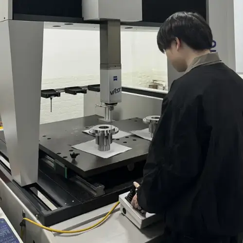
CNC Inspection & Measurement of Tolerances
Tolerance control only works when the inspection method matches the requirement. Many tolerance failures do not come from machining but from trying to measure tight features with tools that cannot verify them reliably.
For general dimensions in the ±0.004 in range, calipers and micrometers are sufficient. As tolerances tighten toward ±0.001 in and below, bore gauges, height gauges, temperature control, and CMM inspection become essential.
If a tolerance cannot be measured consistently, it cannot be controlled in production.
What Limits CNC Machining Accuracy?
Machine rigidity and thermal stability
Heat and cutting forces cause machines to move. Good machines reduce this effect but never eliminate it.
Tool deflection and wear
Cutting tools bend under load and change size as they wear. At tight tolerances, this becomes a dominant source of error.
Material properties
Different materials respond very differently to cutting forces and heat, directly affecting repeatability.
Part geometry and fixturing
Long features, thin sections, and weak clamping allow parts to move during machining and after release.
Machining strategy
Roughing, finishing, and toolpath choices determine how much internal stress remains in the part.
Why Choose JeekRapid for CNC Machined Parts
Tolerance decisions only matter if the process can hold them consistently. That comes from machining experience, process control, and disciplined inspection.
JeekRapid supports CNC projects across aluminum, steel, titanium, and engineering plastics with stable dimensional control for both prototype and production work. Standard production tolerances around ±0.002 in are routine, and high-precision features down to ±0.0004 in and tighter can be achieved on controlled features when justified by design.
Before cutting begins, geometry, tolerance targets, material behavior, and inspection methods are reviewed together so tolerance risk is identified early, not discovered after parts are finished.
If you are holding a drawing right now and wondering whether those tight tolerances are really necessary, that conversation is exactly where good projects begin.For programs involving low volume CNC machining, tolerance decisions have an even greater impact on unit cost and production yield.
What we take into account for your project:Don’t let overly tight tolerances consume your profit. In many projects, relaxing unnecessary ±0.001 in requirements to ±0.003 in can reduce per-part cost by 15–25% without affecting function or reliability.
Ready to get your CNC parts machined with confidence? Submit your drawings and get a CNC machining quote from JeekRapid.JeekRapid provides full-scale CNC machining services with documented process control for tolerance-critical components.
Tolerance requirements in CNC machining cannot be evaluated in isolation. Machine capability, material behavior, and process planning all influence whether a specified tolerance can be achieved consistently. A broader engineering discussion that connects these factors together can be found here:
→ CNC Machining Explained: Machines, Materials, Tolerances, and Practical Engineering Decisions
FAQ
What is the tolerance of CNC machining?
Typical CNC tolerances range from ±0.004 in for standard production to ±0.0004 in for high-precision features.
Is higher precision always better?
Not necessarily. Higher precision increases machining difficulty, tool wear, inspection time, scrap risk, and cost. If tighter tolerances do not improve function or safety, they usually reduce production efficiency.
Why does tighter tolerance increase price?
Because machining slows down, tools wear faster, inspection becomes more complex, scrap risk rises, and more process controls are required to hold those dimensions consistently.