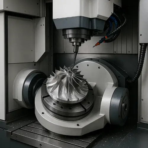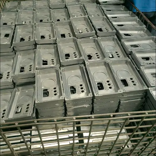
CNC machining thin-wall parts is used to produce lightweight housings, panels, ribs, brackets, covers, and structural components with reduced wall sections. These features save weight and space, but they also lose stiffness as material is removed. A wall that looks stable in CAD can flex under the cutter, move after unclamping, or fall outside tolerance during final inspection.
For many supported aluminum parts, wall thicknesses around 0.8–1.0 mm are a practical starting range. That is not a universal machining limit. Wall height, length, curvature, material, cutter reach, clamping method, and tolerance can matter more than the nominal thickness. A short supported rib may be machined thinner than a long free-standing wall in the same alloy.
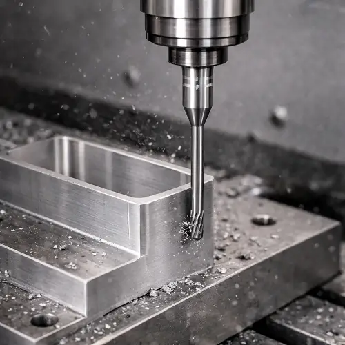
What Is Thin-Wall CNC Machining?
Thin-wall CNC machining refers to milling or turning parts with sections that have low stiffness relative to their height, length, or overall size. There is no single thickness at which every part becomes “thin-walled.” The feature becomes a thin-wall machining problem when cutting force, clamping pressure, heat, or released material stress can move it enough to affect the required dimensions or shape.
Common examples include aluminum electronic enclosures, aerospace brackets, instrument housings, lightweight robotic components, medical-device housings, thin covers, internal ribs, and large pockets surrounded by reduced wall sections. These parts are often machined from a larger block, leaving only a small fraction of the original material in the finished component.
The main difficulty is not simply removing the material. It is keeping the remaining structure stable while roughing, finishing, unclamping, and inspecting the part.
What Is the Minimum Wall Thickness for CNC Machining?
The minimum machinable wall thickness depends on more than material. A short curved wall with support at both ends can remain stable at a thickness that would be unreliable on a long, straight, unsupported edge. Deep pockets also require longer tools, which add another source of deflection.
The following ranges are practical starting points for early design review, not guaranteed limits for every geometry.
| Material | Practical starting range | Main machining concern |
|---|---|---|
| Aluminum alloys | Around 0.8–1.0 mm | Elastic deflection, spring-back, and large unsupported panels |
| Magnesium alloys | Around 0.6–0.8 mm with good support | Low stiffness and deformation during handling or unclamping |
| Titanium alloys | Commonly 1.0 mm or more | Higher cutting force, heat concentration, and residual stress |
| Steel and stainless steel | Commonly 1.0 mm or more | Cutting load, heat, tool pressure, and distortion after stress release |
| Engineering plastics | Often 1.0–1.5 mm or more | Heat, clamping pressure, material recovery, and long-term creep |
A smaller number may still be possible on a compact feature with strong backing and moderate tolerance. A thicker wall may still be difficult if it is tall, long, interrupted by holes, or surrounded by deep material removal. The minimum wall thickness should therefore be reviewed together with wall height, unsupported length, material condition, and required tolerance.
For broader wall-thickness decisions covering ordinary CNC parts as well as thin sections, see our CNC machining wall thickness guide.
Why Are Thin-Wall Parts Difficult to Machine?
Thin walls have less stiffness to resist the side force generated by a milling cutter. As the tool engages the wall, the material can bend away from the cutting edge. The cutter then removes less material than the program expects. Once the tool passes, the wall springs back, leaving taper, uneven thickness, or a surface that measures differently at the top and bottom.
Vibration becomes more likely as the wall gets taller and more flexible. The wall and cutter can both move during the cut, producing chatter marks, inconsistent surface finish, and dimensional variation along the feature. A roughing operation may appear stable because more material is still present, while the problem only becomes visible during the last finishing passes.
Heat also affects the result. Thin sections change temperature quickly and may expand during machining. After cooling, the part can shift again. If a large amount of material is removed from one side of a billet, released residual stress can produce bowing or twisting even when the cutting parameters were reasonable.
Clamping can create a separate error. A thin housing or plate may be pulled flat by the fixture and measure correctly while it remains clamped. Once released, it returns toward its natural shape and no longer meets flatness or profile requirements. Inspection should therefore consider the part’s free state, not only its condition inside the fixture.
How Does Material Affect Thin-Wall Machining?
Aluminum is the most common material for thin-wall CNC parts because it cuts with relatively low force and is widely used for lightweight housings and structural components. Its main challenge is elastic movement. Long aluminum walls can flex during finishing and spring back afterward, affecting wall thickness, straightness, flatness, and parallelism.
Magnesium also cuts with low force and can support relatively thin features under good conditions. Its lower stiffness makes large free edges vulnerable during machining, unclamping, handling, and later assembly. Reliable support is often more important than pushing the cutting speed.
Titanium combines higher cutting force with poor heat dissipation. Thin titanium walls can respond to tool pressure, concentrated heat, and residual stress at the same time. The process normally requires lower and more stable cutting loads, shorter tool reach where possible, and enough time for controlled finishing rather than aggressive material removal.
Steel and stainless steel increase load on the cutter and thin section. Stainless steel also work-hardens if the tool rubs instead of cutting cleanly. A strategy that works on an aluminum wall of the same dimensions may create much more deflection, heat, and tool wear in stainless steel.
Engineering plastics behave differently from metals. Their lower cutting forces help, but heat, clamping pressure, moisture condition, and elastic recovery can change the final dimensions. Sharp tools and limited heat input are important, while very thin unsupported walls may move during machining and continue to relax afterward.
How Do Wall Height, Length, and Support Affect Stability?
Wall thickness alone does not describe machining difficulty. Height-to-thickness ratio gives a better indication of how easily a wall may bend. A 1 mm wall that is 5 mm high behaves very differently from a 1 mm wall that is 30 mm high.
Short aluminum ribs supported at both ends may sometimes be machined at height-to-thickness ratios around 15:1. More compact features can go higher when tool reach is short and cutting pressure is well controlled. These ratios should be treated as project-specific feasibility references, not general production guarantees.
Unsupported length matters as well. A long straight wall acts like a flexible beam under side load. Curved walls, shallow arcs, ribs connected to a solid base, and walls tied into surrounding geometry gain stiffness from their shape. Adding a return, rib, local radius, or support connection can improve machinability without increasing the entire wall thickness.
Openings near a thin wall reduce support. Large holes, slots, sharp transitions, and closely spaced pockets can leave narrow sections that move independently. Sudden changes from thick to thin material also concentrate stress and may cause the part to shift late in the machining sequence.
How Are Thin-Wall Parts Machined Without Deformation?
Stable thin-wall machining begins with the sequence of material removal. Roughing should leave enough stock around the wall to support it. The feature is brought close to its final shape gradually instead of machining one side to full depth while the opposite side remains heavy.
When both sides of a wall are accessible, alternating cuts between them helps balance cutting force and material stress. Machining one side completely before touching the other can push the wall in one direction and create unequal stress release. Layer-by-layer or level-by-level cutting keeps the remaining section more balanced.
Light radial engagement reduces sideways pressure on the wall. Axial depth can sometimes remain productive when the cutter and setup are stable, but the final passes should remove a small and consistent amount of stock. Uneven finishing allowance causes one area to see more tool load than another, which changes deflection along the wall.
A sharp cutter with low runout is important. Worn edges push and rub rather than shear cleanly, adding heat and lateral force. Tool diameter and flute length should be selected so the cutter is as short and rigid as access allows. A tool that can physically reach the bottom of a feature is not automatically rigid enough to hold the wall straight.
Climb milling is often used for finishing on rigid CNC equipment because it can reduce rubbing and produce a cleaner surface. However, toolpath direction should be planned around wall support and the direction in which cutting force pushes the material. Some parts benefit from finishing passes taken in alternating or controlled directions rather than applying force repeatedly to the same unsupported side.
Coolant or air flow should remove chips without applying excessive pressure to a fragile feature. After machining, the part should be allowed to cool and should be measured after clamping force has been released. This separates temporary in-process movement from the final free-state condition.
What Fixtures Are Used for Thin-Wall Parts?
Fixturing is one of the main controls in thin wall machining. Thin-wall fixtures should support the part without forcing it into a shape that disappears after unclamping. Standard vise jaws may be sufficient while the blank is still thick, but later operations often need soft jaws machined to match the part, full-contact nests, custom fixtures, or backing plates.
Soft jaws spread clamping load over a larger area and can locate the part using stronger features instead of pressing directly on a thin wall. A close-fitting support insert may be placed inside a housing or behind a wall to resist cutter pressure. Sacrificial material can also be left in the design and removed only after critical surfaces are finished.
Vacuum fixtures are useful for thin plates and panels when enough surface area is available to generate holding force. The plate still needs uniform backing; otherwise vacuum can pull it against an uneven surface and reproduce that shape during machining.
Low-melting support materials, waxes, removable fillers, or bonded backing may be considered for unusually delicate geometries, but they add preparation and cleaning steps. They should be used only when conventional support cannot provide enough stability and when the part material and later finishing process are compatible.
Re-clamping should be minimized. Every new setup introduces a chance for the part to move or be distorted differently. When multiple setups are unavoidable, stable datums and controlled clamping force help maintain the relationship between walls, holes, and mating surfaces.

What Problems Occur During Thin-Wall Machining?
Tapered wall thickness is a common sign of deflection. The upper edge may measure correctly while the lower or less-supported area remains thicker because it moved away from the cutter. Repeating the same toolpath without changing support or cutting load may not correct the problem consistently.
Chatter appears as repeating waves or marks on the wall. It can come from excessive tool reach, weak workholding, an unsupported feature, or a cutting speed that excites vibration in the wall. Reducing feed alone is not always the answer; a very light rubbing cut can make the finish worse and generate more heat.
Bowing and twisting often appear after unclamping. This may indicate uneven fixture pressure, unbalanced stock removal, or residual stress in the original material. Machining both sides more symmetrically, adding an intermediate release and re-clamping stage, or using stress-relieved stock may improve stability.
Wall collapse or edge damage can occur near holes, slots, and free ends where the structure is weakest. Burrs are also more difficult to remove from a flexible edge because manual pressure can bend or mark the feature. Edge-breaking requirements should be realistic and included in the process plan rather than treated as cleanup after inspection.
Parts may also pass local thickness checks and still fail profile, flatness, or assembly. A few point measurements do not always capture the complete shape of a large thin panel. Inspection should match the functional requirement and the condition in which the part will be assembled.
How Should Thin-Wall Parts Be Designed for CNC Machining?
Use the thickest wall that still meets weight, space, and functional requirements. Reducing a wall below the level needed by the design adds machining risk and cost without improving the part. If only one local area needs clearance, thinning the entire structure may not be necessary.
Keep wall height and unsupported length as short as the design allows. Curvature, return flanges, ribs, and connections to solid regions add stiffness. Gradual transitions between thick and thin areas distribute stress more effectively than abrupt steps and sharp internal corners.
Avoid placing deep pockets on both sides of a thin wall unless the machining sequence can reach and support them properly. When two-sided removal is necessary, provide useful datum surfaces and enough surrounding material for stable clamping during intermediate operations.
Tolerance should follow function. A wall that provides clearance does not need the same thickness, profile, or parallelism control as a sealing or locating surface. Tightening every dimension increases finishing and inspection effort while narrowing the process window. Our CNC machining tolerances guide explains how unnecessary precision affects repeatability and cost.
Clearly identify the critical condition on the drawing. If the part must be flat only after assembly, that requirement differs from free-state flatness. If wall thickness controls weight but not fit, state the acceptable range rather than forcing a tight bilateral tolerance without functional benefit.
When Is CNC Machining Not Suitable for Thin Walls?
CNC machining works well for prototypes, low-volume components, and complex parts that need integrated thin sections, holes, pockets, and precision surfaces. It becomes less attractive when the design consists mainly of a large, uniformly thin shell or panel with little need for machined detail.
Sheet metal forming, stamping, die casting, extrusion, or molding may be more economical for high-volume thin-wall parts. A formed enclosure can maintain a consistent thin section without removing most of a thick block as chips. Secondary CNC machining can then add critical holes, sealing faces, or mounting features.
Process choice should consider quantity, material, wall geometry, tolerance, surface requirements, and tooling cost. A feature may be technically machinable but still be a poor production decision if it requires slow finishing, delicate fixtures, frequent adjustment, and high scrap risk.
Conclusion
Thin-wall CNC machining is controlled by the complete structure, not one minimum thickness number. Material, wall height, unsupported length, curvature, cutter reach, machining sequence, fixture support, tolerance, and residual stress all affect whether the finished part remains stable.
Supported aluminum walls around 0.8–1.0 mm are a reasonable starting reference for many projects, while more demanding materials and long unsupported features need additional thickness or a more controlled process. The most reliable results come from leaving support during roughing, balancing material removal, using sharp and rigid tools, applying light finishing cuts, and checking the part after unclamping.
JeekRapid reviews thin-wall housings, panels, brackets, ribs, and structural components before production. If your part includes reduced wall sections, deep pockets, tight profile requirements, or large unsupported surfaces, upload the CAD model and 2D drawing for a machining review.