Anyone who has machined copper knows it doesn’t behave like most metals. A cut can look clean one moment and start smearing the next. The same traits that make copper valuable—high conductivity, rapid heat transfer, and consistent electrical performance—also make it sensitive to tool sharpness, chip flow, and small shifts in clamping.
If you’ve worked with pure copper, brass, bronze, or beryllium copper, you’ve likely seen how quickly the surface finish changes when chip evacuation falls behind or when the edge loses just a bit of sharpness. This guide brings together practical machining behavior, alloy characteristics, tolerances, and shop-floor strategies that help produce stable, predictable results.
What Is CNC Machining of Copper?
CNC machining of copper focuses on shaping copper and copper-alloy components with controlled accuracy while preserving conductivity, heat performance, and dimensional stability. Electrical interfaces, thermal surfaces, and RF geometries depend on copper’s inherent properties—and machining must protect those characteristics instead of overwhelming them.
Why CNC machining is preferred for copper components
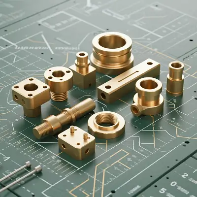
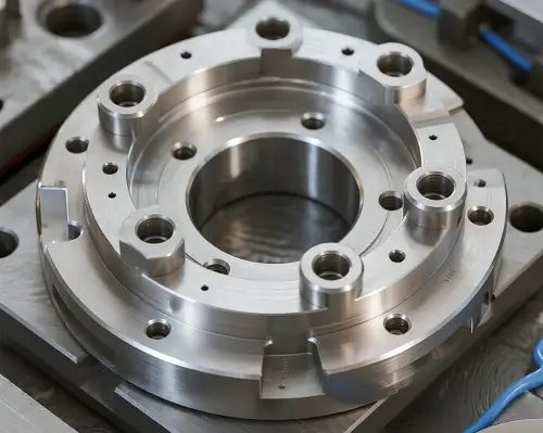
Terminals, switches, heat spreaders, semiconductor components, connectors, and RF housings require flatness, surface integrity, and precise geometry—qualities casting or stamping rarely achieve. CNC machining delivers predictable control over tolerance stack, edge quality, and functional surfaces.
How copper behaves during machining
In most shops, copper isn’t a force problem—it’s a heat and chip behavior problem. A tool that cuts beautifully in the morning may start leaving drag lines after lunch. Chip evacuation, rigidity, and temperature stability often decide whether finishing goes smoothly or becomes a slow cleanup process.
Why Is Copper Difficult to Machine?
Surface drag and micro-scratching
Soft copper alloys deform instead of fracturing cleanly. Even slight rubbing or edge wear produces drag lines or smear marks. If you’ve machined pure copper before, you’ve probably seen this happen even when everything seems set correctly.
Chip-control challenges
Copper chips stay continuous and tend to pack quickly. Once chips fill the flutes, the tool starts recutting material, and the finish degrades almost instantly.
Thermal instability
Copper expands rapidly under localized heat and contracts again during inspection. Thin walls and long sealing faces may measure differently depending on when you check them.
Edge-sharpness sensitivity
Copper reveals tool wear before you see it. A barely-rounded edge increases cutting force and burr height immediately.
Common CNC Methods and Equipment for Machining Copper
Copper machining is less about force and more about controlling engagement, heat, and chip flow. These strategies are common in shops that work with copper regularly:
High-speed milling strategies
Higher spindle speeds with light chip loads promote shearing instead of rubbing—especially useful on pure copper and annealed tempers.
Precision cutting tools
Razor-sharp edges, polished flutes, and non-ferrous tool geometries reduce chip welding and minimize smear marks.
Low-lubrication or air-blast machining
Air blast or MQL clears chips without disturbing cut stability. You’ll see this often on heat spreaders or thick copper plates.
Trochoidal and adaptive toolpaths
Adaptive toolpaths maintain stable chip thickness and reduce heat concentration—helpful for pockets and large copper surfaces.
Multi-axis machining
5-axis setups improve approach angles, reduce burrs, and help stabilize thin sections.
High-rigidity machines with thermal control
Rigid spindles, balanced holders, and thermal compensation systems reduce drift on long faces or flatness-critical copper parts.
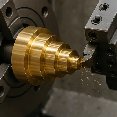
High-speed turning for brass
Free-cutting brass performs exceptionally well on auto lathes with polished carbide inserts, making it ideal for connectors and fittings.
Micro-machining for fine features
Micro tools and high-frequency toolpaths are essential for terminals, miniature slots, and fine electrical features.
Tooling Choices and Cutting-Parameter Strategies
Tool materials and coatings
Uncoated carbide or thin PVD coatings preserve edge sharpness better than heavy coatings. Edge geometry matters more than hardness.
Cutting speeds and feed rates
Copper supports high SFM, but the feed must be strong enough to shear. Too light, and you’ll rub; too heavy, and burr height increases.
Radial and axial engagement
Small radial engagement with deeper axial steps stabilizes chip formation and reduces rubbing.
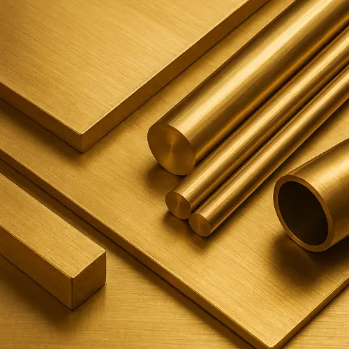
Types of Copper Materials Used in CNC Machining
Pure copper (C11000)
High conductivity and ductility; prone to drag and surface defects.
Brass (H59, H62, C36000)
Predictable machining behavior and excellent chip control. Ideal for high-volume fittings and connectors.
Bronze (tin and aluminum bronze)
Higher strength and wear resistance, with good dimensional stability under heat.
Beryllium copper (BeCu)
High elasticity and fatigue strength—common in contacts, probes, and precision mechanical components.
Achievable Tolerances for Copper Alloys
Pure copper
±0.03 mm is realistic unless staged finishing is used.
Brass
±0.01–0.02 mm is common due to stable cutting behavior.
Bronze and BeCu
Dimensional stability is excellent; tool wear becomes the main limiting factor.
Factors Affecting Surface Quality
Edge wear
Even slight edge rounding leads to visible smear patterns.
Chip evacuation
If chips aren’t clearing, the surface will show streaks or pits almost immediately.
Heat distribution
Localized temperature swings can cause tiny distortions that only appear after cooling.
Workholding Strategies for CNC Machining Copper
Soft jaws and protective interfaces
Aluminum or polymer jaws prevent marking on pure copper and brass parts.
Managing deformation
Thin sections often need backers, tabs, or soft supports to prevent micro-movement during finishing.
Thermal expansion considerations
Letting parts cool lightly clamped often improves final flatness more than expected.
Burr Formation and Edge-Quality Control
Why burrs form
Copper stretches before breaking, creating rolled edges.
How to reduce burrs
Maintain sharp tools, use higher chip loads, and keep engagement stable.
Deburring methods
Brush deburring, micro-abrasives, vibratory finishing, and thermal deburring depending on geometry.
Surface Finishing Options for CNC-Machined Copper
As-machined surfaces
Pure copper may show tonal variation even with correct parameters.
Polishing
Diamond pastes and fine abrasives achieve low-Ra surfaces for electrical and thermal interfaces.
Plating choices
Nickel, tin, silver, and gold flash depending on corrosion or conductivity needs.
Recommended Cutting-Parameter Ranges
| Alloy | Typical SFM | Chip Behavior | Notes |
|---|---|---|---|
| Pure Copper | High | Continuous | Sensitive to heat and edge wear |
| Brass (C36000) | Very high | Breaks cleanly | Best for high-volume machining |
| Bronze | Moderate | Harder chips | Higher cutting force required |
| BeCu | Moderate–high | Predictable | Good accuracy, higher tool wear |
Typical Applications of CNC-Machined Copper
Electrical and Electronic Components
Terminals, contact pads, grounding plates, connector pins, EMI/RF shielding pieces, and heat spreaders used in power and signal systems.
Mechanical and Fluid Components
Brass valves, threaded fittings, pump components, precision housings, and corrosion-resistant adapters.
High-Reliability Mechanisms
Beryllium-copper probe pins, springs, switch elements, and sensor components requiring elastic stability.
Key Advantages of CNC Machining Copper
Copper alloys provide unmatched electrical/thermal performance, stable dimensional behavior, and strong productivity in free-cutting grades. If your part relies on conductivity, heat flow, sealing, or mechanical resilience, copper remains one of the most capable engineering materials.
How Much Does Copper CNC Machining Cost?
Cost drivers
Geometry complexity, alloy type, surface-finish requirements, and burr control all impact the final machining price.
Material influence
Brass machines quickly and economically. Pure copper and BeCu require tighter control and more finishing time.
Cycle-time impact
For many copper parts, finishing cycles and burr removal determine the true cost, not roughing.
Typical cost range for copper CNC parts
Across most machining shops, copper components fall in a higher price tier than aluminum or mild steel because of slower feeds, heat sensitivity, and additional finishing work. Simple brass connectors might range $15–$40 per piece, while pure copper terminals, plates, and heat spreaders typically fall between $40–$120 depending on tolerance and surface requirements. Complex BeCu components—especially those needing polishing or multi-axis machining—commonly reach $150–$300 in prototype runs. These aren’t fixed numbers, but they reflect the pricing engineers often encounter.
Summary and Request for Quote
Stable copper machining comes from understanding how each alloy reacts to heat, pressure, and tool engagement. Pure copper needs techniques that prevent smearing; brass supports fast, clean machining; bronze and BeCu reward rigid setups with excellent stability.
If you want a second set of eyes on a copper design, feel free to send the model over. Sometimes a small geometry change saves a surprising amount of machining time.
JeekRapid will review your file and return a clear, practical quote within 24 hours.
When comparing copper-based materials for machining applications, understanding the broader differences between copper, brass, and bronze helps engineers make better material decisions.
For a full breakdown of performance, machinability, and cost, see our detailed guide on
Copper vs Brass vs Bronze.
FAQ About CNC Machining Copper
1. Why does copper scratch even when the tool still looks sharp?
Because copper is extremely sensitive to edge rounding. A tool can “look fine” but already be rubbing instead of cutting.
2. Why is pure copper so much harder to machine than brass?
Pure copper smears and drags easily, while brass breaks chips cleanly and behaves predictably.
3. What tolerances do most copper parts achieve in real shops?
Pure copper: around ±0.03 mm
Brass: ±0.01–0.02 mm under stable conditions
4. Do copper alloys require uncoated tools only?
Not necessarily, but sharpness is everything. Many shops stick to uncoated or thin-coated tools to protect edge geometry.
5. Why do copper parts sometimes warp slightly after machining?
Localized heat during cutting can shift dimensions, especially on thin walls. Parts often move slightly as they cool.