Dowel pin hole tolerance should be selected according to how the pin works in the assembly. One component normally uses a press-fit hole to retain the pin, while the mating component uses a slip-fit hole for accurate location and easier assembly. Hole diameter alone is not enough. Position, datums, material, coating and inspection also affect the final fit.
A common drawing mistake is giving both mating holes the same tight tolerance. The individual holes may pass inspection, but a small difference in hole spacing can prevent the two parts from fitting together. Tightening every tolerance is not always the solution because the two holes usually perform different jobs.
What Is Dowel Pin Hole Tolerance?
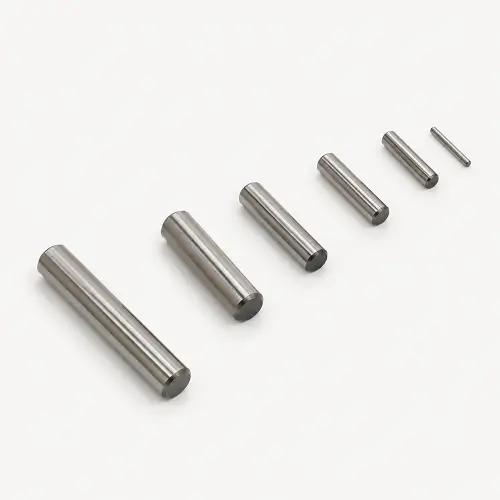
Dowel pin hole tolerance defines the acceptable size variation of a hole that receives a locating pin. The required limits depend on whether the hole must retain the pin, allow the pin to slide or provide a closely controlled transition between those conditions.
In a typical two-part assembly, the first component uses a press fit to hold the dowel pin. The mating component uses a slip fit so it can be installed and removed without excessive force. The pins establish the position of the parts, while bolts provide the clamping force.
Dowel pins and bolts should not be treated as interchangeable locating features. A bolt clearance hole allows the fastener to pass through and accommodate normal assembly variation. A dowel pin hole controls the position of the component more closely. When alignment matters, the pins should establish location and the bolts should secure the joint.
Should a Dowel Pin Use a Press Fit or Slip Fit?
Use a press fit when the dowel pin must remain secured in one component. Use a slip fit in the mating component when the parts must locate accurately but still assemble and separate without damage.
Press-Fit Dowel Pin Hole
A press-fit hole is smaller than the actual pin diameter. The resulting interference holds the pin in place. This arrangement is commonly used in fixture bases, machine housings, alignment plates and other components that permanently retain the dowel pin.
The required interference depends on the pin tolerance, part material, wall thickness, hole depth and installation method. More interference does not automatically produce a stronger or more reliable assembly. Excessive interference can expand an aluminum boss, distort a thin wall, crack an engineering plastic or make future pin replacement difficult. These factors should be considered when selecting the press fit tolerance for CNC machined parts.
This is why a fit that works in a thick steel plate should not automatically be copied into a thin aluminum housing. The surrounding geometry must be able to support the installation force and the pressure created by the pin.
Slip-Fit Dowel Pin Hole
A slip-fit hole is larger than the maximum pin diameter. The controlled clearance allows the mating component to slide over the pin while retaining useful positioning accuracy.
Too much clearance reduces repeatability. Too little clearance makes the assembly sensitive to burrs, contamination, temperature changes, surface treatment and small hole-position errors. The objective is not to specify the tightest possible slip fit. It is to provide enough clearance for reliable assembly without losing the locating function.
A transition fit falls between a definite press fit and a free slip fit. Depending on the finished pin and hole sizes, it may require light installation force or have almost no noticeable clearance. If the pin must remain fixed, a defined press fit is easier to manufacture and inspect. If the component must be removable, a guaranteed slip fit is normally more predictable.
What Hole Size Should Be Used for a Dowel Pin?
The correct dowel pin hole size must be chosen from the actual pin limits, not only its nominal diameter.
Consider a simplified example using a nominal 0.2500 in dowel pin. If the pin specification allows the diameter to reach 0.2502 in, a removable mating hole must remain larger than 0.2502 in when a guaranteed slip fit is required. A hole with a minimum diameter of 0.2500 in would not guarantee clearance, even though its nominal size appears to match the pin.
The same logic applies to a press fit. The hole limits must remain below the relevant pin limits by the amount of interference required for that material and assembly. It is not enough to write the same nominal diameter for the pin and hole and assume the manufacturing process will create the correct fit.
This example explains the relationship between the tolerances; it is not a universal fit recommendation. The final limits should follow the actual pin specification and project requirements.
There is no single dowel pin hole tolerance suitable for every CNC machined part. The designer should consider the smallest and largest possible pin, hole material, available wall thickness, installation method, operating temperature, surface treatment and required locating repeatability before releasing the drawing.
Why Does One Part Use a Press Fit and the Other Use a Slip Fit?
When both components use tight press-fit holes, even a small difference in hole spacing can stop the parts from fitting together.
Suppose two dowel pins are installed in a base plate. The mating component also contains two tightly fitted holes. For the assembly to work, both hole diameters, the distance between the holes and their position relative to the datums must agree closely at the same time.
The first pin may enter correctly while the second pin does not line up. Applying more force can damage the pin, deform the hole or pull the assembly away from its intended position. Making both hole patterns even tighter may increase machining cost without correcting the underlying design problem.
In drawing reviews and assembly checks, one of the most common problems is a pair of holes that both pass diameter inspection but do not align with the two pins at the same time. A more reliable arrangement is normally to press the pins into the base component and provide controlled slip-fit holes in the removable component.
For locating pins placed farther apart, center-distance variation and temperature change become more important. Some assemblies use one round locating hole together with a relieved hole or diamond pin. The round location controls the main position, while the relieved location controls orientation without unnecessarily restricting movement in every direction.
The design should constrain only the movement that needs to be controlled. Adding more tightly fitted locating features can make assembly less reliable rather than more accurate.
Does Reaming Produce an Accurate Dowel Pin Hole?
Reaming improves hole diameter, roundness and surface finish, but it does not reliably correct a hole that is already in the wrong position.
A dowel pin hole is commonly spotted and drilled slightly undersize before the reamer removes a controlled amount of material to produce the final diameter. Leaving too much stock increases the cutting load and can result in an oversized, tapered or rough hole. Leaving too little stock can cause the reamer to rub instead of cutting consistently.
Reaming is suitable when the starting hole is already correctly located and the main requirement is a consistent finished diameter. It is commonly used for dowel holes, locating shafts and alignment features that need better size control than ordinary drilling can provide.
However, the reamer generally follows the existing hole. If the drilled hole is off position, the reamed hole may have an accurate diameter and clean internal surface while its center remains misplaced. A drawing should therefore not use the word “REAM” as a substitute for defining the required finished size and position.
Reaming vs Boring for Dowel Pin Holes
Reaming is generally faster for repeatable, standard-size dowel holes. Boring gives the machining process more control over the final center, diameter, straightness and relationship to other features.
Boring may be more appropriate when the starting hole needs positional correction, the finished diameter is nonstandard or several bores must maintain accurate alignment. It is also commonly selected for bearing seats, sleeves and other internal features where both diameter and bore geometry affect the assembly.
Circular interpolation with an end mill can provide another option when several diameters are needed or tooling flexibility is important. Its achievable roundness and size consistency depend on the machine, cutter, workholding, material and toolpath.
The correct process follows the function of the hole. Standard locating holes may be produced by CNC drilling followed by reaming, while boring machining provides more control when bore position, diameter and alignment are critical.
Why Can Dowel Pin Holes Pass Inspection but Fail Assembly?
A dowel pin hole can meet its diameter tolerance and still fail assembly because hole size and hole position control different conditions.
A plug gauge can confirm that the hole is within a specified size range. It does not prove that two holes have the correct center distance or that the complete pattern is correctly located relative to the functional datums.
Hole size determines whether a pin can enter an individual hole. Hole position determines whether the complete pin pattern can enter the mating component. Datums determine where that pattern is located in relation to the surfaces that position the part during assembly.
This is why two holes can both pass a size check while the mating component still does not fit. The problem may be center distance, true position, angular error through the hole depth or the relationship between the selected datum and the real assembly surface.
Burrs at the hole entrance and coating inside the bore can create similar symptoms. Material distortion or temperature differences between inspection and assembly may also affect very close fits.
When the first pin enters but the second pin does not, the pattern should be checked before increasing both hole diameters. Poor hole position in CNC machining can prevent assembly even when each hole passes its individual size inspection.
How Should Dowel Pin Holes Be Specified on a Drawing?
A clear dowel pin hole callout should define the finished diameter, fit, depth, position and datum relationship rather than only naming the intended machining process.
If an entrance chamfer is necessary for assembly, it should be specified. The drawing should also make clear whether the hole is intended for a press fit or slip fit and whether the final size applies before or after surface treatment.
Notes such as “REAM” or “DOWEL HOLE” are not enough on their own. They may identify the intended process or use, but they do not define the acceptable finished diameter, position or relationship to the mating component.
Functional surfaces should guide datum selection for CNC machined parts. A surface that is convenient for machining or measurement is not always the correct datum for representing how the component is located during assembly.
When two mating components are involved, the supplier should receive enough information to review both sides of the fit. A machine shop can manufacture one isolated part exactly according to its drawing without knowing that its tolerances conflict with the mating component.
How Do Material and Surface Treatment Affect Dowel Pin Fit?
The same amount of interference should not be applied blindly to steel, aluminum and engineering plastics.
Aluminum is softer than hardened steel and is more likely to deform around an aggressive press fit. A thin aluminum wall may expand locally during pin installation and affect nearby features.
Stainless steel resists local deformation better, but tool wear, heat and work hardening can make close hole tolerances more difficult to maintain. Engineering plastics may change dimension with temperature, moisture and clamping pressure. A plastic hole measured immediately after machining may behave differently after the material stabilizes.
Anodizing, plating, painting and other finishes can reduce the usable hole diameter. A slip-fit hole that works correctly before anodizing may become too tight afterward.
The drawing should therefore state whether a critical hole will be masked during finishing, reamed after finishing or allowed to receive coating. This sequence should be reviewed before quotation rather than corrected during final assembly.
How Are Dowel Pin Holes Inspected?
Different inspection methods answer different questions. A plug gauge provides a quick go/no-go check for hole size, while a bore gauge measures the internal diameter more directly. A coordinate measuring machine can inspect true position and the relationship between the hole pattern and its datums.
For an assembly-critical dowel hole, inspection may also need to consider taper, hole depth, center distance and the orientation of the hole axis. Measuring only the diameter can miss the actual cause of an assembly problem.
However, not every locating hole needs a complete CMM report. Inspection should match the function of the feature, production quantity and documentation required by the customer. Specifying unnecessary inspection can increase cost without improving assembly performance.
Why Is a Dowel Pin Hole Too Tight?
If one pin will not enter one hole, check the actual pin diameter, minimum hole diameter, entrance burr, roundness and surface treatment. Do not assume the finished pin is exactly equal to its nominal diameter.
If the first pin enters but the second does not, the more likely problem is hole position or center distance. Increasing the second hole’s clearance or revising the locating method may be more effective than tightening both patterns.
If the hole becomes tight only after anodizing or plating, the finishing allowance or masking requirement was probably not fully considered. Reaming the hole after finishing may be possible, but that decision should account for corrosion protection and the intended appearance of the part.
These problems should be reviewed as a complete fit system. The pin, both mating holes, datums, material and finishing process all influence the final assembly.
How Much Does a Precision Dowel Pin Hole Cost?
A reamed dowel hole generally costs more than a standard drilled hole because it adds a finishing operation and closer inspection. Cost increases further when the hole pattern requires tight true position, multiple setups, boring, post-finish reaming or a CMM report.
The most economical approach is not to apply tight tolerances to every hole. It is to identify which hole retains the pin, which hole allows assembly and which dimensions actually control the position of the mating components.
Clear design intent allows the machining supplier to concentrate process control and inspection on the features that affect function instead of adding cost to noncritical dimensions.
What Should Be Provided for a Dowel Pin Hole Quote?
For a reliable quotation, send the 3D CAD model and a 2D drawing showing the pin specification, finished hole limits, press-fit or slip-fit requirement, depth, true position and functional datums. The material, surface treatment, quantity and inspection requirements should also be identified.
When possible, provide drawings for both mating components. Reviewing only one part may not reveal a conflict between the two hole patterns or fit tolerances.
If the parts already have an assembly problem, include the measured pin diameters, actual hole sizes and center distance. This information helps determine whether the problem comes from diameter, position, material distortion or surface treatment.
Get a Dowel Pin Hole Machining Quote
Dowel pin hole tolerance is not one number that can be copied into every drawing. A reliable assembly usually uses a press fit to retain the pin in one component and a controlled slip fit in the mating component.
Reaming can improve hole size and surface finish, but it cannot guarantee correct position. Diameter, true position, datums, material, finishing and inspection must work together if the parts are expected to assemble consistently.
If a drawing includes press-fit and slip-fit dowel holes, send both mating part drawings when possible. JeekRapid can review the pin specification, hole limits, true position, material and finishing sequence before quotation.
Upload your CAD files and 2D drawings for a free DFM review and project-specific CNC machining quote.