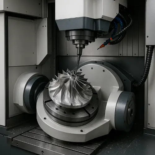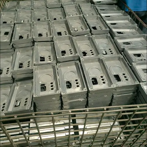
Medical CNC machining is used to produce accurate metal and plastic components for diagnostic equipment, surgical instruments, laboratory systems, monitoring devices, and other medical equipment. It is especially suitable for prototypes and low-volume parts that require reliable dimensions, clean edges, and repeatable assembly without dedicated production tooling.
However, a medical application does not make every dimension critical, and an ISO 13485-certified quality system does not automatically make every machined part suitable for implantation or sterile use. The drawing still needs to define the material, functional tolerances, surface finish, cleaning, inspection, and documentation required for the specific device.
For engineers and purchasing teams, the first question should not simply be whether a CNC machine can produce the geometry. The more important question is whether the machining process, material, inspection plan, and finishing requirements can produce a part that fits its assembly and meets the project’s quality expectations.
What Medical Device Parts Can Be CNC Machined?
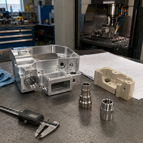
CNC machining is suitable for medical device parts that need accurate holes, flat mounting faces, controlled wall thickness, threaded features, sealing surfaces, or several features aligned from common datums. It works with both metals and engineering plastics and can support design changes without requiring a new mold.
Typical CNC machined medical parts include equipment housings, instrument components, brackets, valve bodies, fittings, connectors, sleeves, test fixtures, and prototype assemblies. Whether a particular part is suitable depends on its geometry, material, tolerance, quantity, and regulatory requirements.
Medical Equipment Housings and Enclosures
Diagnostic equipment, laboratory instruments, patient monitoring systems, and fluid-control devices often use machined housings or enclosures. Aluminum is common when low weight, corrosion resistance, thermal performance, and an anodized appearance are required. Stainless steel or engineering plastics may be selected when chemical resistance, strength, or electrical insulation is more important.
The difficult features are not always visible on the outside. Internal pockets, thin walls, connector openings, threaded inserts, sealing faces, and hole patterns can determine whether the housing assembles correctly. If the walls are too thin or material is removed unevenly, the housing may distort after it is released from the fixture.
Cosmetic requirements should also be identified before machining. A housing that will be bead blasted and anodized needs different handling from an internal bracket with an as-machined finish. Areas that must remain free of coating should be marked clearly on the drawing.
Surgical Instrument Components
CNC milling and turning can produce handles, pivots, adapters, couplings, shafts, sleeves, and other mechanical components used within surgical instruments. These parts may require corrosion-resistant materials, smooth transitions, controlled edges, and surfaces that can withstand the specified cleaning or sterilization process.
The intended use matters. A non-patient-contact instrument component does not necessarily have the same material, surface, cleaning, or documentation requirements as a component that contacts tissue. The device manufacturer should define these requirements rather than relying on the machining supplier to infer them from the part name.
Sharp internal corners, narrow slots, small threads, and intersecting holes should be reviewed carefully. Even when the main dimensions pass inspection, a hidden burr or rough transition can create problems during assembly or use.
Precision Valves, Fittings, and Connectors
Medical and laboratory equipment may use machined valve bodies, fluid fittings, pneumatic connectors, threaded adapters, and precision sleeves. These parts often depend on the relationship between bores, threads, sealing surfaces, and outside diameters.
For these components, hole size alone may not be enough. A bore may also require controlled roundness, surface finish, concentricity, or position relative to another feature. Threads must be clean, sealing faces must remain free from damage, and intersecting passages must be inspected for burrs and trapped chips.
CNC turning is often practical for round fittings and sleeves, while milling may be added for flats, ports, mounting holes, or other secondary features.
Medical Device Prototypes and Test Fixtures
CNC machining is particularly useful during medical device development because it allows engineers to test parts made from production-intent materials. A machined prototype can be used to evaluate fit, stiffness, thread engagement, sealing, assembly access, and dimensional stability before the design moves into a larger production run.
Test fixtures, inspection fixtures, assembly aids, and laboratory tooling are also common CNC projects. Although these parts may not become part of the finished device, their accuracy can affect how the device is assembled, measured, or validated.
Producing a small first batch provides an opportunity to confirm the drawing and inspection method. If a critical hole, datum, or surface finish is unclear, it is better to identify the issue during the prototype stage than after a larger order has entered production.
The most suitable machining process depends on the geometry. Housings and brackets are commonly produced by CNC milling. Round fittings and sleeves are often turned. Complex multi-surface parts may benefit from 5-axis machining when fewer setups improve the positional relationship between features. Precision holes may require drilling followed by reaming or boring rather rather than drilling alone.
How to Choose Materials for CNC Machined Medical Parts
Material selection for a medical device part should begin with its actual operating conditions. Strength matters, but corrosion exposure, cleaning chemicals, temperature, weight, electrical behavior, wear, and dimensional stability may be just as important.
“Medical grade” is not a complete material specification. The drawing or purchase documentation should identify the exact alloy or polymer grade and any certification, traceability, or biocompatibility requirements associated with it.
| Material | Common Applications | Points to Confirm Before Machining |
|---|---|---|
| 6061 aluminum | Equipment housings, brackets, covers and mounting plates | Anodizing, cosmetic surfaces, coating buildup and assembly fit |
| 316L stainless steel | Instrument components, fittings and fluid-handling parts | Material condition, passivation, surface finish and cleaning |
| Titanium | Lightweight, corrosion-resistant and high-strength parts | Exact grade, certification, surface requirements and machining cost |
| PEEK | Insulating, chemical-resistant and lightweight components | Exact material grade, service temperature and dimensional stability |
| Delrin | Fixtures, guides and non-critical mechanical components | Wear, moisture exposure, cleaning method and plastic tolerance |
Consider an aluminum diagnostic equipment housing with a locating bore, four mounting holes, an internal electronics pocket, and an anodized exterior. The locating bore may require ±0.001 in because it controls assembly, while the outside profile and internal clearance pocket may use ±0.005 in. If anodizing is applied, the bore may need masking or a final after-finish tolerance. This approach protects the functional fit without adding unnecessary precision to the entire part.
Aluminum 6061 is a practical option for many external housings, instrument frames, brackets, and equipment components. It machines efficiently and accepts anodizing well, but it is not automatically suitable for every patient-contact or high-temperature application. Anodizing can also change dimensions on close-fitting features, so masking and post-finish requirements should appear on the drawing.
316L stainless steel is selected when corrosion resistance, strength, and cleaning resistance are important. It can be used for instrument components, fittings, and fluid-handling parts, but it machines more slowly than aluminum and may work harden if the cutting process is poorly controlled. Passivation and final surface requirements should be specified before quotation.
Titanium provides high strength at a relatively low weight and offers good corrosion resistance. It is valuable in demanding applications, but the exact grade must be stated. Titanium retains heat near the cutting edge and creates higher tooling and cycle-time costs than aluminum. JeekRapid’s guide to titanium CNC machining explains how grade, geometry, tool access, and tolerance affect manufacturability and price.
PEEK can be useful where a part needs chemical resistance, electrical insulation, low weight, or stable performance at elevated temperatures. Medical applications may require a specific PEEK grade and supporting documentation. General industrial PEEK should not be treated as interchangeable with a grade approved for a particular medical use. More material and machining considerations are covered in the PEEK CNC machining guide.
Delrin is economical and easy to machine for fixtures, guides, insulators, and mechanical components that do not require the performance of PEEK. It can produce clean features and low-friction surfaces, but the design must still account for temperature, moisture, clamping pressure, and less stable plastic tolerances.
The machining supplier can explain how each material behaves during cutting. Final approval of material suitability, sterilization compatibility, biocompatibility, and regulatory use remains with the device manufacturer and its applicable specifications.
What Tolerances Do Medical CNC Parts Need?
Typical CNC machining tolerances for medical equipment components range from ±0.005 in for general features to approximately ±0.001 in for controlled mating features. Selected bores, locating diameters, and other critical features may require ±0.0005 in, but this level of precision should be applied only where part function justifies the additional machining and inspection.
These figures are practical starting points rather than guaranteed values for every part. Achievable tolerance depends on the material, feature size, wall thickness, geometry, workholding, finishing process, and inspection method.
| Feature | Practical Tolerance Range | Typical Application |
| General milled dimensions | ±0.003 to ±0.005 in | External profiles, clearance pockets and non-critical surfaces |
| Controlled mounting features | ±0.001 to ±0.002 in | Mounting faces, hole patterns and assembly locations |
| Turned diameters | ±0.001 to ±0.002 in | Sleeves, fittings, shafts and connectors |
| Precision bores | ±0.0005 to ±0.001 in | Locating pins, controlled fits and valve components |
| Hole position | Approximately 0.001 to 0.003 in | Dowel holes, connector patterns and aligned assemblies |
| General machined surface finish | Ra 63 to 125 µin | Most structural and internal surfaces |
| Controlled functional surface | Approximately Ra 32 to 63 µin | Sliding, sealing or closely mating surfaces |
Not every medical component needs the smallest tolerance shown in the table. A machined equipment housing, for example, may use ±0.005 in on its general outside dimensions while applying ±0.001 in only to locating holes, connector positions, or mating surfaces. Using ±0.001 in across the entire drawing would increase cycle time and inspection without necessarily improving assembly.
Material behavior must also be considered. Aluminum usually allows stable dimensional control, but a thin aluminum housing may move after heavy pocketing. Stainless steel generates more cutting force and may distort in thin sections. Titanium holds heat near the cutting edge, while PEEK and Delrin respond to temperature and clamping pressure. The same tolerance cannot be applied to all materials and geometries with the same level of risk.
Datums are just as important as numerical tolerances. A hole can meet its diameter requirement and still cause an assembly failure if its position is controlled from the wrong surface. Drawings should identify the surfaces that locate and orient the component and relate critical holes, bores, and sealing features to those datums.
Surface finishing should be included in the tolerance plan. Anodizing, plating, polishing, and other processes can change close-fitting dimensions or soften functional edges. If a bore, thread, sealing face, or locating feature must meet its tolerance after finishing, the drawing should state that requirement clearly.
Thin walls create a different problem. A wall may move under clamping pressure, vibrate during finishing, or change shape after the part is removed from the fixture. Plastics can also expand with temperature or deform when held too tightly. In these cases, simply adding a tighter drawing tolerance does not make the feature easier to produce. Wall support, roughing sequence, tool pressure, material condition, and inspection temperature all affect the result.
Inspection must match the feature. Calipers and micrometers are suitable for many general dimensions, while tight bores, true position, flatness, and multi-feature relationships may require bore gauges, height gauges, or CMM inspection. Features approaching ±0.0005 in also require more stable temperature, tooling, fixturing, and measurement conditions.
The JeekRapid guide to CNC machining tolerances provides additional information about practical tolerance ranges, GD&T, inspection methods, and the cost of unnecessary precision.
How Are Burrs, Cleanliness, and Quality Controlled?
Dimensional accuracy is only one part of medical component quality. A part may pass a dimensional report and still create problems because of a hidden burr, trapped chip, damaged sealing edge, polishing change, or unclear cleaning requirement.
Burrs are especially common where holes intersect, where a drill exits into an internal cavity, at the bottom of threads, and along narrow slots. These areas may be difficult to see and difficult to reach with standard deburring tools. The machining plan should consider how the feature will be cut, inspected, and cleaned before production begins.
Deburring also needs limits. Removing a sharp burr is necessary, but excessive hand finishing can round a functional edge, enlarge a small hole, reduce thread engagement, or change a sealing surface. Drawings should identify edges that require a controlled break and edges that must remain sharp for function.
Internal passages deserve additional attention. Chips and cutting-fluid residue can remain in deep holes, intersecting passages, or blind cavities. Air cleaning alone may not remove particles trapped behind an internal shoulder. Depending on the geometry and customer requirements, cleaning may require flushing, ultrasonic cleaning, visual magnification, borescope inspection, or another project-specific method.
It is important to distinguish normal shop cleaning from a validated medical cleaning or sterile process. A CNC supplier may remove machining oil, loose chips, and visible residue, but that does not automatically mean the part is sterile, cleanroom processed, or ready for patient contact. If the project requires a defined cleanliness level, approved cleaning agent, passivation process, controlled packaging, or contamination record, those requirements must be stated before quotation.
Surface finishing can introduce additional risk. Polishing may improve appearance or reduce roughness, but it also removes material. Aggressive polishing around an edge, bore, or sealing surface can alter a dimension that was correct after machining. Finishing and inspection should therefore be planned as one process rather than treated as unrelated operations.
ISO 13485 provides a quality management framework for medical device-related manufacturing. In practical terms, it supports controlled procedures, document management, traceability, inspection records, corrective action, and process consistency. These controls help a supplier follow approved requirements across prototypes and repeat orders.
ISO 13485 certification does not automatically qualify every machined component for implantation, sterilization, or a specific regulatory submission. The device manufacturer must still define applicable material standards, validation requirements, cleanliness, packaging, labeling, and documentation.
JeekRapid operates under ISO 9001 and ISO 13485 quality management systems. For a medical machining project, the required inspection records, material documentation, traceability, surface treatment, cleaning, and packaging should be reviewed with the drawing before production.
This prevents a common problem in which parts are dimensionally correct but cannot be accepted because a required certificate, inspection report, or process record was not requested at the quoting stage.
How Much Does Medical CNC Machining Cost?
Medical CNC machining commonly ranges from about $60 to $200 per part for relatively simple prototypes and from $200 to $1,000 or more for complex, tight-tolerance components. Material, geometry, quantity, finishing, inspection, and documentation can move the actual price outside these ranges.
The following figures can be used for early budgeting. They are not fixed quotations.
| Medical CNC Part Type | Typical Early Budget Range for Low-Quantity Parts |
| Simple 6061 aluminum bracket or mounting plate | $60–$150 |
| Aluminum equipment housing or enclosure | $120–$400 |
| Basic stainless steel fitting, sleeve, or connector | $100–$300 |
| Precision stainless steel component with controlled bores | $200–$600 |
| PEEK equipment or instrument component | $150–$500 |
| Titanium precision component | $300–$1,000+ |
| Complex multi-surface or 5-axis medical part | $500–$1,500+ |
These ranges are most useful for prototypes and very small quantities. Once setup, programming, tooling, and first-part inspection are distributed across a repeat order, unit prices may decrease substantially. However, higher quantity does not remove the cost of demanding materials, slow machining, special cleaning, or detailed inspection.
A small part is not always inexpensive. A stainless steel fitting with two intersecting passages, a precision bore, a sealing face, and internal burr requirements may cost more than a larger aluminum plate. The smaller part requires more controlled operations and may be more difficult to inspect and clean.
Material has a direct effect on cost. Aluminum generally machines faster and has lower tool wear. Stainless steel and titanium require slower cutting conditions and more process control. PEEK can machine efficiently, but certified stock is expensive, and excess material removal increases waste.
Tolerance also changes price. A general tolerance of ±0.005 in is more economical than applying ±0.001 in throughout the drawing. Precision bores or locating features approaching ±0.0005 in may require finishing passes, tool compensation, temperature control, and additional inspection. Applying tight tolerances only to functional features is one of the most effective ways to control cost.
Post-processing and quality documentation should be included in the initial request. Anodizing, passivation, polishing, masking, specialized cleaning, CMM reports, material certificates, and lot traceability all require additional work. Adding these requirements after machining can lead to delays, dimensional problems, or a revised price.
For an accurate quotation, provide the 3D CAD model, 2D drawing, material grade, quantity, critical tolerances, surface finish, cleaning requirements, and required inspection documents. JeekRapid can then review the geometry and provide a project-specific price rather than relying on a broad online estimate.
Conclusion
Successful medical CNC machining depends on more than producing the correct geometry. Material grade, functional tolerances, datum selection, burr control, surface treatment, cleanliness, inspection, and documentation all affect whether a medical device component can be assembled and accepted.
The best results begin with a clear CAD model and a complete 2D drawing. Mark the features that affect fit, sealing, alignment, or device performance and distinguish them from ordinary clearance and cosmetic dimensions. Cleaning, finishing, inspection, and traceability requirements should also be defined before the part is quoted.
JeekRapid supports CNC machined metal and plastic parts from prototype development through low-volume and production orders. Its ISO 9001 and ISO 13485 quality systems provide a framework for controlled manufacturing and inspection, while project-specific requirements are reviewed against the drawing before production.
Upload your CAD files and 2D drawings for a free DFM review within 24 hours. Include the material, quantity, critical tolerances, surface finish, cleaning, and inspection requirements so JeekRapid can review the project accurately.