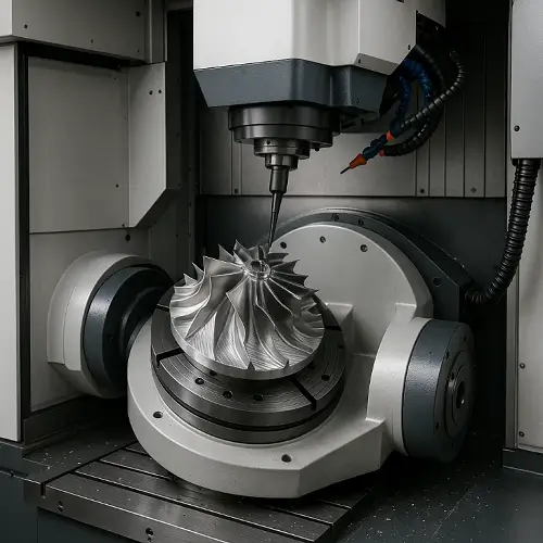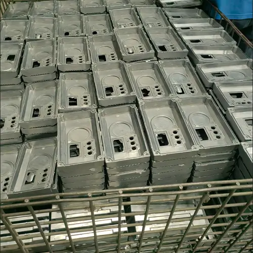
CNC drilling uses programmed machine motion and a rotating cutting tool to create accurately located holes in metal or plastic parts. It is fast and repeatable for through holes, blind holes, hole patterns, and thread preparation. However, drill-only quality has limits. Tight fits, corrected alignment, and fine bore finishes may require reaming or boring after drilling.
For a designer or buyer, the important question is not simply whether a CNC machine can make a hole. The real questions are whether the drill can reach the required depth, evacuate chips, hold the specified diameter and position, and exit without leaving an unacceptable burr. Those decisions affect tool life, cycle time, inspection, and part cost.
What Is CNC Drilling?
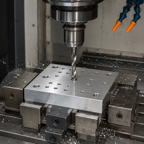
CNC drilling is a subtractive machining process in which a computer-controlled machine positions a drill and feeds it into a workpiece to produce a hole. The operation may take place on a CNC machining center, CNC mill, CNC lathe, or dedicated CNC drilling machine. The control system uses programmed coordinates, tool offsets, spindle speed, feed rate, and drilling cycles to reproduce the same hole pattern across multiple parts.
The cutting action is similar to conventional drilling, but the location and motion are controlled by the machine rather than by hand. This improves repeatability, especially when a part contains many holes or when those holes must relate to machined datums, pockets, or external profiles.
CNC hole drilling is often the first operation in a longer hole-making sequence. A drilled hole may remain as produced when it is only a clearance, fluid, or access hole. It may also be tapped, reamed, bored, counterbored, or countersunk when the assembly requires threads, a close fit, a flat fastener seat, or a specific surface finish.
How Does CNC Drilling Work?
The CNC drilling process begins with the drawing and CAD model. A programmer identifies the hole diameter, depth, location, tolerance, material, and any secondary features. The part is then located from suitable datums, clamped securely, and machined with enough access for the drill and coolant.
For a straightforward hole, the machine moves the drill to the programmed coordinate, starts the spindle, feeds to depth, and retracts. Short holes in stable materials may use one continuous feed. Deeper holes or materials that produce long chips may need a peck-drilling cycle, which periodically retracts the tool so chips can clear. Pecking is useful when required, but unnecessary pecking adds cycle time and can increase tool wear.
Spot drilling may be added before the main drill when the entry surface, tool geometry, or positional requirement creates a risk of drill walking. It is not automatically necessary for every modern carbide drill. The spot geometry must also suit the final drill; a poorly matched spot can load the drill corners instead of improving accuracy.
After drilling, the machine may chamfer or deburr the entrance and exit, create threads, or finish a critical bore. Inspection then confirms the features that matter to function. A pin gauge can check size quickly, while a coordinate measuring machine may be needed for true position relative to the specified datums.
What Types of Holes Can CNC Drilling Produce?
CNC drilling operations can produce several hole forms, but each one creates different machining and drawing requirements.
| Hole type | Practical design issue | What to specify |
|---|---|---|
| Through hole | Breakout can create an exit burr | Diameter, location, and deburring requirement |
| Blind hole | Drill-point geometry remains at the bottom | Usable depth or full depth, plus bottom requirement |
| Threaded-hole preparation | Tap-drill size and bottom clearance affect thread depth | Thread standard, class, depth, and whether the hole is blind |
| Deep hole | Chip evacuation, heat, and drill drift become more difficult | Diameter, total depth, entry condition, and critical alignment |
| Small hole | The drill has low stiffness and limited chip space | Diameter, depth, quantity, and whether the size is truly necessary |
| Intersecting hole | The drill may enter or exit an open cavity unevenly | Hole order, burr access, and whether internal burrs are allowed |
| Angled-entry hole | The cutting edges can engage unevenly and push the drill sideways | Entry angle and whether a flat landing can be added |
A conventional twist drill leaves a conical bottom in a blind hole. If the drawing gives only the cylindrical depth without defining how it is measured, the supplier and customer may interpret the requirement differently. For a practical explanation of usable depth, drill-point allowance, and flat-bottom options, see Blind Hole Bottom Shape.
What Tools Are Used for CNC Drilling?
The correct CNC drilling tool depends on hole diameter, depth-to-diameter ratio, material, tolerance, machine rigidity, coolant delivery, and production volume. There is no single drill that is best for every hole.
High-speed steel twist drills are tough, economical, and useful for general work, especially where the setup is less rigid. Solid carbide drills are stiffer, resist wear, and support higher productivity and better consistency on capable machines. Indexable drills use replaceable inserts and are often economical for larger diameters, although their attainable geometry and finish differ from those of solid carbide tools.
Spot drills establish a controlled starting location when walking is a concern. Flat-bottom drills can reduce the remaining cone in a blind hole and may help on certain interrupted or angled conditions, but they are not a universal substitute for preparing a stable entry surface. Gun drills and other specialized deep-hole tools use guided geometries and dedicated coolant flow when an ordinary twist drill can no longer control chips or straightness reliably.
Toolholding matters as much as the drill itself. Excessive holder or spindle runout makes one cutting edge carry more load, which can enlarge the hole, shorten tool life, and increase breakage risk. A short, rigid setup with controlled runout gives the drill a much better chance of producing a consistent result.
What Accuracy and Tolerances Can CNC Drilling Achieve?
CNC drilling accuracy is not one number. Hole diameter, true position, straightness, roundness, cylindricity, and surface finish describe different aspects of a drilled hole. A hole can be within its size tolerance and still fail assembly because its position is wrong. It can also enter at the correct coordinate but drift as depth increases.
Under rigid, well-controlled conditions, modern solid-carbide drilling systems can produce approximately H8–H9 hole quality in applications identified by their tool manufacturers. That capability should not be treated as a universal promise for every part. Actual CNC drilling tolerance depends on diameter, depth, material, drill geometry, runout, workholding, entry surface, coolant, and how the feature is inspected.
For ordinary clearance or passage holes, a drilled finish is often sufficient. When a hole must locate a dowel, carry a bearing, seal against a mating component, or create a controlled sliding or press fit, drill size alone is usually not a safe design strategy. The drilled hole can instead leave material for a controlled finishing operation.
Position tolerance must also be selected from assembly needs. Do not tighten hole diameter simply to compensate for a position problem. If a bolt pattern needs assembly clearance, size and true position should be evaluated together. If bore alignment to another feature is critical, the manufacturing plan must control both features from appropriate datums, preferably without an avoidable re-clamping step.
CNC Drilling vs Boring and Reaming
Drilling creates a hole efficiently from solid material. Boring uses a single-point cutting tool to enlarge an existing hole and can improve its diameter, alignment, and relationship to other machined features. Reaming removes a small, controlled amount of material from a prepared hole to improve size consistency and surface finish.
Use drilling alone when the hole functions as a general clearance, access, fluid, or thread-preparation feature and the drill-produced geometry meets the drawing. Consider boring machining when the bore diameter, alignment, or positional relationship needs correction. Consider reaming when an existing hole already follows the correct path but needs a closer final size and smoother finish.
These operations are not competitors in every case. A precision hole may be drilled first and then bored or reamed. The most economical process is the shortest sequence that reliably satisfies the functional requirement—not the process with the most impressive tolerance on paper.
What Are the Advantages and Limitations of CNC Drilling?
The main advantage of CNC drilling is repeatable productivity. A machining program can reproduce a complete pattern of holes with consistent coordinates, depths, feeds, and speeds. Multiple features can often be drilled, chamfered, and tapped in one setup, reducing manual layout and avoiding unnecessary handling between operations.
CNC drilling is also flexible. Tool changes allow one machine to produce different diameters, depths, and hole preparations on the same component. This makes the process useful for prototypes, mixed-feature parts, and production quantities. When holes are machined in the same setup as surrounding features, their relationship can be controlled more effectively.
Its limitations come from the drill’s geometry and stiffness. A drill tends to follow the path it establishes rather than correct an existing hole. It may walk on an inclined surface, deflect in a deep hole, produce a conical blind-hole bottom, or leave a burr at breakthrough. Chips and heat must travel out through limited flute space. As tolerances become tighter or depth increases, additional tooling, coolant, slower cycles, or secondary finishing may be necessary.
Why Are Deep and Small Holes Difficult to Drill?
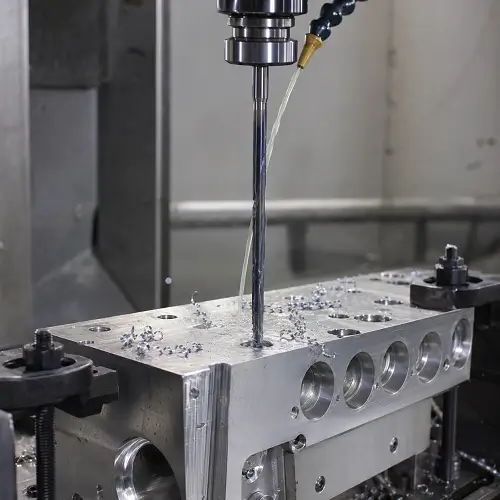
Deep-hole drilling becomes difficult because chips have farther to travel and coolant has more difficulty reaching the cutting edge. The longer tool is also less resistant to deflection. As the depth-to-diameter ratio increases, chip recutting, heat, drill drift, poor surface finish, and breakage become more likely.
There is no single depth ratio at which every hole changes from easy to difficult. As a planning guide, short holes around 3×D or less are generally more straightforward. Holes in the 3–8×D range often benefit from purpose-designed drills and through-tool coolant. Around 12×D and beyond, deep-hole strategy, pilot geometry, coolant pressure, tool guidance, and machine capability become increasingly important. These are process-planning ranges, not guaranteed limits.
Small-hole drilling has the same problems in a smaller, less forgiving tool. A small drill has low bending strength, narrow flutes, and very little room for chips. Minor runout, a hard inclusion, or an aggressive feed change can break it. A hole that is both small and deep is therefore much more demanding than either its diameter or depth suggests by itself.
Before specifying a deep or small hole, ask whether the functional passage really needs that diameter and depth. Increasing diameter, reducing depth, opening the hole from the opposite side, converting a blind hole to a through hole, or allowing a plugged cross-drilled passage can reduce risk and cost. The right alternative depends on whether flow, sealing, appearance, strength, or access controls the design.
A Practical CNC Drilling Review Example
JeekRapid regularly reviews deep holes around 4.7 in before programming. A depth value alone is not enough to approve the operation. The engineering review also considers hole diameter, depth-to-diameter ratio, material, whether the hole is blind or through, drill-entry geometry, coolant access, chip evacuation, and the straightness or positional relationship required at the far end.
For deeper holes around 6.3–7.1 in, manufacturability is evaluated case by case. A larger through hole in aluminum with a perpendicular entry may be practical, while a much smaller blind hole of the same depth in stainless steel can require specialized tooling, additional cycles, or a design change. If the original geometry creates excessive drift or breakage risk, practical alternatives include increasing the diameter, reducing the depth, drilling from two directions, or replacing one long passage with intersecting holes. This review prevents the drawing from treating all holes of the same depth as equally machinable.
What Problems Occur During CNC Drilling?
Drill walking occurs when the drill does not start on its intended axis. Common causes include an angled, curved, rough, or interrupted entry surface; excessive runout; and unsuitable spotting. Providing a perpendicular landing, milling a small flat, or choosing the correct starting method can improve location.
Oversized or inconsistent holes often point to runout, tool wear, unstable holding, built-up edge, or the wrong cutting data. A nominal drill diameter does not guarantee that exact finished size. If size is functional, it must be toleranced, produced with a capable process, and verified with a suitable gauge.
Chip packing is especially serious in blind and deep holes. Packed chips increase torque and heat, score the bore, damage the drill, and can trap the tool. Through-tool coolant, appropriate flute geometry, a suitable drilling cycle, and enough chip-clearance space near the bottom all help. Simply adding more pecks is not always the best answer; the cycle should match the tool and material.
Drill breakage is usually a process symptom rather than an isolated accident. Runout, excessive feed, recutting packed chips, poor coolant delivery, work hardening, and a weak or overly long tool can all contribute. Breakage becomes particularly expensive in a finished or high-value part because removing the fragment may be impossible without damage.
Exit burrs form as the remaining material becomes too thin to support the cutting load at breakthrough. Feed control, backup material, an accessible chamfer, or a change in hole direction may reduce the burr. Intersecting holes need special attention because an internal burr may be difficult to inspect or remove after machining.
How Does Material Affect CNC Drilling?
Material changes cutting forces, heat generation, chip form, tool wear, and burr behavior. The same drill geometry and cutting parameters should not be copied across every alloy.
Aluminum usually drills quickly, but ductile grades can create long chips and built-up edge. Sharp tools, polished or suitable coated flutes, and effective chip evacuation help prevent material from welding to the cutting edge. Aluminum can also form substantial breakout burrs if the drill is dull or poorly supported.
Carbon and alloy steels require the drill grade, coating, speed, and coolant to match hardness and strength. Stainless steel combines toughness with a tendency to work-harden. Dwelling or rubbing instead of cutting can harden the next layer and make the operation progressively worse, so a stable feed and sharp tool are important.
Titanium retains heat near the cutting edge and places high demands on coolant delivery and tool condition. Plastics present a different problem: heat may soften the material, while elastic recovery can affect measured hole size. Some plastics also need special attention to cracking, chip stringing, and burr control. Material specification should therefore be available before the supplier commits to tooling and tolerance.
How Should Holes Be Designed for CNC Drilling?
Good hole design gives the drill a stable entry, a realistic path, enough room for chips, and an accessible way to manage burrs. Start by using standard drill diameters when the function permits. A nonstandard diameter may need extra tooling or a secondary interpolation operation without improving the assembly.
Whenever possible, place the hole axis perpendicular to the entry surface. A drill entering an angled or curved face engages one cutting edge first and is pushed sideways. If the hole must be angled, adding a machined flat landing or allowing an appropriate multi-step process can improve reliability.
Avoid making blind holes deeper than the usable function requires. The drawing should account for the drill-point cone and allow clearance below a thread, pin, or inserted component. If a flat bottom is functionally necessary, state it explicitly; do not assume a standard drill produces one.
Use a practical depth-to-diameter ratio. A slightly larger passage may be much easier to drill and clean than a long, narrow one. For intersecting holes, consider which hole should be machined first and where the internal burr will go. Drilling the larger intersecting hole first can sometimes reduce burr formation when the smaller hole breaks into it, but the best sequence depends on geometry and access.
Apply tight tolerances only to functional holes. A mounting clearance hole, a dowel hole, and a bearing bore do not need the same diameter, finish, or inspection method. If one pattern contains both ordinary and critical holes, identify them separately so the entire part is not priced as precision-bore work.
Also leave enough material between holes, edges, thin walls, and pockets to resist drilling forces. Closely spaced features can distort, break through, or leave fragile edges. If the surrounding geometry is already thin, the machining sequence and support strategy may become as important as the hole itself.
What Hole Details Should Be Shown on a Drawing?
A useful hole callout tells the manufacturer what the feature must do without forcing an unnecessary method. Show the hole diameter and its tolerance, whether it is through or blind, and the required depth. For a blind hole, clarify whether depth refers to the full drill point, the cylindrical wall, or the usable feature depth.
Locate the hole or pattern from clear datums. If assembly depends on location, use a true-position requirement with the intended datum reference frame rather than relying only on plus/minus coordinate dimensions. State whether the tolerance applies at maximum material condition when that bonus tolerance reflects the assembly function.
Add thread designation, class, and thread depth where applicable. Identify counterbores, countersinks, spotfaces, chamfers, sealing seats, or flat-bottom requirements separately. If burrs could interfere with flow or assembly, define the affected edges and an acceptable condition rather than using a vague note that is impossible to inspect.
Critical bores may also need surface finish, roundness, cylindricity, straightness, or orientation controls, but each control should serve a functional need. Include material and condition, quantity, and any inspection or certification requirement that affects acceptance. A complete drawing lets the manufacturer choose drilling, drilling plus reaming, or drilling plus boring before cost and schedule are committed.
Conclusion
CNC drilling is an efficient way to create repeatable holes, but a successful hole depends on more than its nominal diameter. Depth, material, entry geometry, chip evacuation, runout, location, burr access, and inspection all influence the result. Drilling is often enough for clearance and passage holes; close-fit or alignment-critical features may need reaming or boring.
The best time to resolve these issues is before production. If your part contains deep blind holes, small-diameter passages, intersecting holes, tight hole patterns, or precision bores, upload your CAD files and drawing for a JeekRapid machining review and quote. The review can identify where drilling alone is appropriate and where a different hole-making sequence will reduce risk.