Gears may look simple, but their teeth have to mesh at the correct position, angle, and spacing for the part to run smoothly. A small error in tooth profile or runout can cause noise, vibration, uneven wear, or poor power transmission.
Gear machining is the manufacturing process used to create the gear blank, cut the teeth, and finish the critical surfaces. Depending on the gear design and production quantity, manufacturers may use CNC milling, hobbing, shaping, grinding, or a combination of these processes.
For someone ordering a custom gear, the important question is not simply how the teeth are cut. Material, gear type, accuracy, heat treatment, bore size, keyways, and quantity all affect the final manufacturing method. Understanding these basics makes it much easier to choose a practical process and prepare a drawing for production.
What Is Gear Machining and How Does It Work?
Gear machining refers to the machining processes used to manufacture gears and their tooth profiles from metal or engineering plastic.
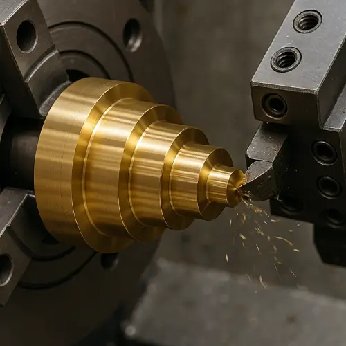
The work normally begins with a gear blank. Turning or milling is used to create the outside diameter, bore, faces, shoulders, and other basic features. The teeth are then produced using a suitable gear cutting method such as milling, hobbing, or shaping.
Some gears can be used after tooth cutting and deburring. Others require heat treatment for higher strength and wear resistance. High-accuracy gears may then go through gear grinding or another finishing process to improve tooth geometry and running performance.
This means gear manufacturing is often a sequence rather than a single machining operation.
For custom parts, CNC machining is frequently used to produce the gear blank, bore, mounting faces, keyways, holes, and other features before or alongside the tooth-cutting operation.
How Are Gears Manufactured?
The manufacturing route depends heavily on what the gear needs to do.
A simple low-load gear may only require machining of the blank and teeth. A transmission gear operating under repeated loads may require alloy steel, controlled tooth geometry, heat treatment, and final grinding.
In a typical gear manufacturing process, the raw material is first cut to size. The blank is then turned or milled to establish the outside diameter, bore, faces, and important datums. Gear teeth are cut after the blank geometry is stable.
After cutting, the tooth edges and other machined features also need to be checked for unwanted burrs. Proper deburring is especially important around tooth edges, bores, keyways, and holes where remaining burrs could interfere with assembly or gear engagement.
The part may then be heat treated, ground, coated, or inspected depending on the drawing.
This sequence matters. For example, cutting every feature to final size before heat treatment may create problems if hardening causes dimensional change. On higher-accuracy gears, manufacturers may intentionally leave finishing allowance and complete certain surfaces after heat treatment.
What Are the Main Gear Machining Methods?
There is no single best way to machine every gear. Gear size, tooth shape, material, quantity, accuracy, and whether the teeth are internal or external all influence the choice.
| Gear Machining Method | Common Use | Main Advantage |
|---|---|---|
| CNC gear milling | Prototypes, custom gears, low-volume parts | Flexible and suitable for many geometries |
| Gear hobbing | External spur and helical gears | Fast and efficient for repeated production |
| Gear shaping | Internal and external gears | Useful where hobbing cannot easily reach |
| Broaching | Internal gears and splines in production quantities | Fast after dedicated tooling is prepared |
| Gear grinding | Hardened, high-accuracy gears | Improves tooth accuracy and finish |
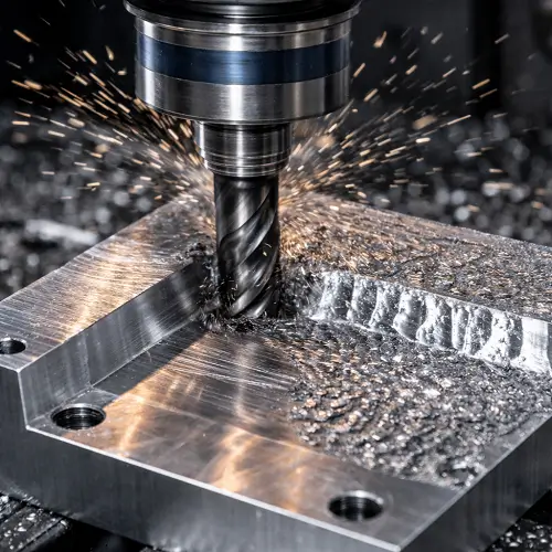
CNC gear milling is particularly useful for prototypes and custom gear machining because it does not always require dedicated gear-cutting tooling. Modern multi-axis machining also gives manufacturers more flexibility when producing unusual geometries or small quantities.
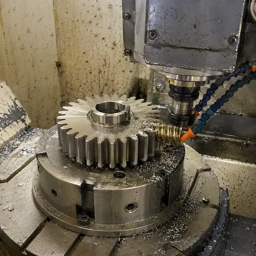
Gear hobbing is different. A rotating hob progressively generates the teeth as the gear blank and cutter move in a controlled relationship. It is widely used for external spur and helical gears because of its productivity.
Gear shaping uses a reciprocating gear-shaped cutter and can produce both external and internal teeth. This becomes useful when part geometry prevents a hob from reaching the required area.
Gear grinding is normally a finishing process rather than the first tooth-cutting operation. It becomes important when hardened gears require better tooth accuracy, smoother running, or tighter control after heat treatment.
For unusual internal profiles or difficult features in electrically conductive materials, Electrical Discharge Machining can also be considered. EDM is not the normal choice for producing ordinary gear teeth, but it can solve specific cases where conventional cutting tools have limited access.
What Is the Difference Between Gear Hobbing, Milling, and Shaping?
For customers, these processes can appear very similar because all three can create gear teeth. The practical differences are flexibility, accessibility, production speed, and tooling.
Gear milling cuts the tooth spaces with a milling cutter. It is flexible and makes sense for prototypes, replacement gears, unusual sizes, and lower quantities where dedicated tooling would add unnecessary cost.
Gear hobbing continuously generates teeth and is generally much more productive when manufacturing suitable external gears in repeated quantities. This makes hobbing common in production gear manufacturing.
Gear shaping is valuable for geometries that are difficult or impossible to hob, especially internal gears or external gears located close to a shoulder.
The correct choice therefore depends on the actual drawing rather than simply choosing the process that sounds most precise.
Can CNC Machines Make Gears?
Yes. Gears can be manufactured using CNC machines, particularly for prototypes, custom gears, replacement parts, and low-volume production.
CNC milling can cut individual tooth spaces using controlled toolpaths. CNC machines can also produce additional features such as bores, keyways, mounting holes, pockets, and complex surrounding geometry as part of the same manufacturing route.
However, CNC milling is not automatically the most economical choice for every gear. If hundreds or thousands of identical external gears are required, dedicated gear hobbing may produce the teeth more efficiently.
This is why CNC gear machining is particularly attractive when flexibility matters, while specialized gear cutting becomes increasingly important when production quantity and cycle time dominate the decision.
What Types of Gears Can Be Machined?
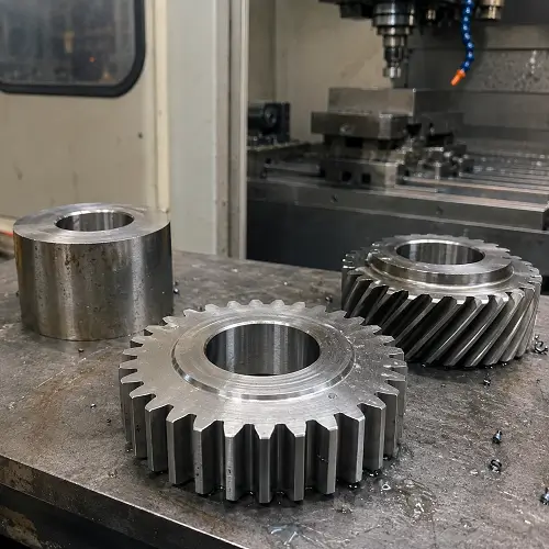
Spur gears are among the most straightforward gears to manufacture. Their straight teeth run parallel to the gear axis, making them suitable for many industrial mechanisms, machines, actuators, and mechanical assemblies.
Helical gears have angled teeth. They generally provide smoother engagement than spur gears but introduce additional manufacturing considerations, including helix angle and direction.
Internal gears place the teeth on the inside diameter of a ring. Their geometry limits tool access, so processes such as gear shaping, broaching, or other suitable machining methods may be selected instead of conventional external hobbing.
Bevel gears, worm gears, racks, and other special gear forms require their own machining strategies. Complex geometry does not necessarily make a gear impossible to machine, but it can change the machine, cutter, setup, inspection method, and cost required to manufacture it.
For this reason, the gear type should be clear on the drawing before a machining process is selected.
What Materials Are Used for Machined Gears?
Steel is one of the most common choices for machined gears because it provides a useful balance of strength, fatigue resistance, wear resistance, and heat-treatment options.
Carbon and alloy steels such as 1045, 4140, and 8620 are used in different gear applications. The correct grade depends on load, expected service life, hardness requirements, and whether the gear will be carburized, induction hardened, nitrided, or treated by another process.
Stainless steel is useful where corrosion resistance matters. Brass and bronze may be selected for particular wear, friction, or corrosion requirements, especially in certain worm gear applications.
Aluminum can also be used for lightweight gears, prototypes, instruments, and applications where high steel-like load capacity is unnecessary. Both 6061 and 7075 are common machining alloys, but their strength, cost, corrosion behavior, and machining characteristics are different. The 6061 vs 7075 aluminum comparison is useful when weight matters but the application does not require a hardened steel gear.
Engineering plastics are another option for light loads, low noise, corrosion resistance, or weight reduction.
Material choice should therefore follow how the gear actually works rather than simply choosing the hardest available material.
How Accurate Is Gear Machining?
Gear accuracy cannot be described by one normal dimensional tolerance alone.
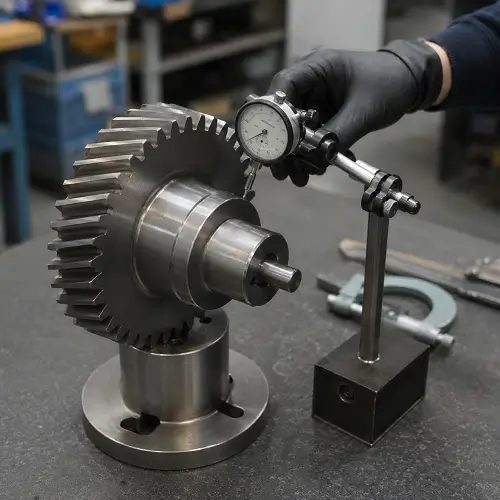
A drawing might specify the bore diameter within ±0.01 mm, but that does not fully describe whether the teeth will mesh correctly. Gear performance is also affected by tooth profile, pitch, lead or helix accuracy, runout, concentricity, and the relationship between the teeth and the bore.
This is an important distinction when ordering precision gear machining.
A gear can have an accurate outside diameter and still run poorly if the tooth geometry is incorrect. Likewise, accurately machined teeth can still create problems if the gear bore is not sufficiently concentric with the tooth form.
The bore itself may therefore need more than ordinary drilling. When bore diameter, roundness, finish, or alignment is important to the gear assembly, boring machining can be used to refine an existing hole before the final gear is completed.
The required accuracy should match the application. A positioning mechanism, low-speed industrial drive, high-speed gearbox, and precision motion system do not necessarily need the same gear quality.
Specifying unnecessarily high accuracy also increases manufacturing and inspection costs. It is usually better to identify which features actually affect fit, motion, noise, and service life.
When Is Gear Grinding Needed?
Gear grinding is normally considered when the required tooth accuracy or surface condition cannot be reliably achieved by the earlier cutting process alone.
One common situation is a hardened steel gear. Heat treatment improves hardness and wear resistance but can introduce small dimensional changes. If tooth accuracy is critical, the teeth can be cut with finishing allowance before hardening and then ground afterward.
Grinding can correct small errors while improving the final tooth surface.
Not every gear needs grinding. For a prototype mechanism, lightly loaded gear, or ordinary industrial component, properly controlled milling or hobbing may already provide adequate performance. Adding grinding when it is not functionally necessary increases both cost and lead time.
Does Heat Treatment Affect Gear Machining?
Yes. Heat treatment can have a major effect on the machining sequence of steel gears.
Processes such as carburizing, induction hardening, nitriding, and through hardening are used to achieve different combinations of surface hardness, wear resistance, strength, and core toughness. But heating and cooling can also cause some distortion.
That is why the relationship between machining and heat treatment should be considered before production begins.
Some gears are machined completely before heat treatment when their final accuracy requirements allow it. Precision gears may be rough machined and tooth cut first, heat treated next, and then finish ground on critical areas.
The correct sequence depends on the material, hardness requirement, tooth accuracy, bore tolerance, and final application.
What Is the Difference Between Gear Machining and Gear Cutting?
Gear cutting specifically refers to creating the gear teeth. Hobbing, shaping, and gear milling are examples of gear cutting methods.
Gear machining is a broader term. It can include manufacturing the gear blank, turning the bore and outside diameter, milling other features, cutting the teeth, machining keyways, deburring, and performing finishing operations.
This difference matters for custom gears because the teeth are only one part of the component.
A customer may also need a precise bearing bore, mounting face, keyway, threaded holes, shaft connection, or other features. All of these features have to work correctly with the gear teeth in the final assembly.
How Much Does Gear Machining Cost?
Gear machining cost depends on much more than the overall diameter of the gear.
A simple spur gear in a machinable material can be relatively straightforward. Cost increases when the part requires an unusual tooth profile, high gear accuracy, difficult material, internal teeth, heat treatment, grinding, multiple setups, or extensive inspection.
Quantity also matters. For one or several prototypes, flexible CNC gear machining may avoid the cost of special production tooling. As quantity increases, hobbing or other dedicated gear manufacturing methods can become more economical because setup and tooling costs are distributed across more parts.
Tolerance is another major cost factor. Requiring very high gear accuracy when the application does not need it can add machining, grinding, and inspection operations without improving the way the final product works.
These cost drivers are similar to many custom machined parts, where material, setup, machining time, tolerance, quantity, finishing, and inspection all affect the quote. For a broader explanation, see CNC machining cost.
For an accurate gear quotation, the manufacturing supplier still needs to see the actual gear specifications rather than estimating from diameter and tooth count alone.
What Information Is Needed for a Custom Gear Machining Quote?
A useful gear drawing should clearly identify the tooth geometry and the rest of the component.
For most custom gear machining projects, the manufacturer needs the gear type, number of teeth, module or diametral pitch, pressure angle, face width, and material. Helical gears also require the helix angle and direction.
The drawing should also show the bore, keyway or spline, mounting features, relevant dimensional tolerances, and any gear quality requirements. If heat treatment, hardness, grinding, coating, or special inspection is required, these details should be specified before quoting.
A 3D CAD model is helpful for understanding the overall geometry, but a 2D drawing remains important when it contains tooth data, tolerances, material, heat treatment, surface finish, and inspection requirements that are not fully defined in the model.
Quantity should also be included. The most economical process for five prototype gears may be very different from the best process for 5,000 production gears.
Conclusion
Gear machining covers much more than simply cutting teeth into a round piece of metal. The final result depends on the gear type, tooth geometry, machining method, material, heat treatment, accuracy requirement, and production quantity.
CNC gear milling provides flexibility for prototypes and custom parts, while hobbing and shaping are useful for different gear geometries and production requirements. When hardened gears require higher accuracy, grinding may be added after heat treatment.
For customers, the most important step is to define how the gear must fit and function. Once the tooth specifications, material, critical dimensions, heat treatment, and quantity are clear, the manufacturing process becomes much easier to plan.
JeekRapid supports custom metal and plastic parts through CNC machining services, including machining, grinding, EDM, inspection, and related manufacturing processes.
Upload your gear drawing or CAD file to JeekRapid and get a quote for your custom machined parts.