For a purchased bushing, use the manufacturer’s recommended housing bore instead of calculating the hole from nominal OD alone. For a custom solid bushing, calculate minimum and maximum interference from the bushing OD and housing-bore limits. In both cases, verify the installed ID because press fitting can reduce the final shaft clearance.
This distinction is important because the word “bushing” covers several different products. A solid machined steel sleeve, bronze bearing, oil-impregnated bushing, thin-wall wrapped bearing, plastic bushing and hardened drill bushing do not necessarily use the same housing tolerance.
A housing bore marked H7 may be correct for one purchased bushing and wrong for another. The right answer begins with the bushing type, its actual dimensional limits and the required condition after installation.
What Is Bushing Fit Tolerance?
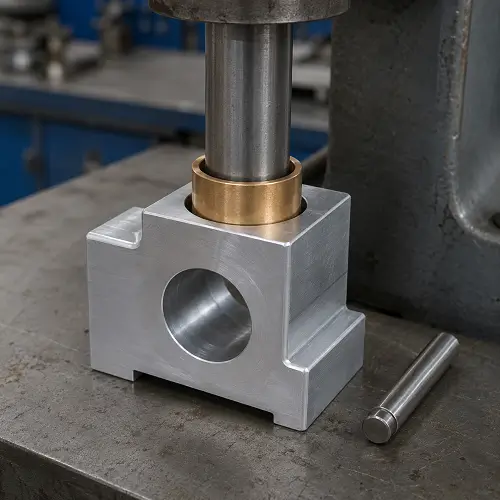
Bushing fit tolerance describes the dimensional relationship between the bushing outside diameter and the bore in the surrounding housing. When the bushing OD is larger than the housing bore, the difference creates interference that holds the bushing in place.
The assembly also contains a second fit between the bushing inside diameter and the shaft, pin or guide passing through it. These two fits are connected. Pressing the bushing OD into the housing can reduce the bushing ID, which changes the final shaft clearance.
For this reason, a bushing cannot be accepted only because its loose outside and inside diameters meet their drawings. The installed condition is what determines whether the bushing stays in the housing and whether the shaft moves correctly.
OD means the outside diameter of the bushing, while ID means its inside diameter. The housing bore is the machined hole that receives the bushing.
What Housing Bore Size Does a Bushing Need?
The correct bushing housing bore depends first on whether the bushing is a purchased standard product or a custom machined component.
For a purchased plain bearing, plastic bushing, wrapped bushing or drill bushing, the manufacturer’s installation-hole tolerance should normally be used. The OD may be intentionally oversized or shaped so that pressing it into the specified housing forms the correct installed ID.
Many metric bushings recommend an H7 housing bore, but H7 is not a universal answer for every product. H7 defines the tolerance zone of the hole; it does not by itself confirm the amount of interference, the installed ID or the shaft clearance. Those results also depend on the bushing’s OD and ID tolerances.
Standard drill bushings may have their own recommended installation-hole limits. Their nominal OD should not simply be copied as the housing-hole size. The supplier’s installation data or hole-size calculator should be followed.
For a custom solid steel or bronze bushing, the housing bore can be selected by calculating the interference created by the bushing OD and housing-bore tolerance limits. If a drawing gives only a nominal bushing OD without its upper and lower limits, a reliable press-fit hole size cannot be determined.
This is the direct answer to a common question such as “What hole size is needed for a 1.0000 in bushing?” The nominal diameter alone is insufficient. The bushing type, actual OD limits and required interference must be known first.
How Is Press-Fit Bushing Interference Calculated?
A custom bushing fit should be checked at both the loosest and tightest possible tolerance conditions.
Minimum interference equals the minimum bushing OD minus the maximum housing bore.
Maximum interference equals the maximum bushing OD minus the minimum housing bore.
Consider a simplified example using a custom solid bushing. Assume the bushing OD is specified from 1.0005 to 1.0008 in and the housing bore is specified from 0.9998 to 1.0000 in.
The minimum interference is 1.0005 minus 1.0000, which gives 0.0005 in. The maximum interference is 1.0008 minus 0.9998, which gives 0.0010 in.
The complete fit therefore provides 0.0005 to 0.0010 in of interference. Checking only the nominal 1.0000 in diameter would have hidden that range.
This calculation identifies the dimensional interference. It does not prove that the range is appropriate for every application. The result still needs to be reviewed against the bushing material, housing material, bore diameter, wall thickness, engagement length, load and installation method.
The minimum condition must provide enough retention to stop the bushing from rotating or moving. The maximum condition must not shrink the bore excessively, crack the housing or require unsafe installation force.
These same tolerance-limit principles apply when calculating a press fit tolerance for CNC machined parts.
How Much Interference Does a Bushing Need?
There is no single amount of interference that is correct for every bushing. Published rules such as a fixed amount per inch of diameter can provide an initial reference for some solid metal parts, but they should not replace the product manufacturer’s installation specification or an application-specific fit review.
A solid steel bushing installed in a thick steel housing can tolerate a different fit from a thin bronze sleeve pressed into an aluminum boss. Even when the nominal diameter is identical, the materials and surrounding geometry respond differently.
Bushing length also affects installation. A longer engagement surface creates more friction and generally requires more pressing force. A thin housing wall may expand under the same interference that a thick housing absorbs with little visible change.
Too little interference can allow the bushing to rotate, move axially or become loose under vibration. Too much interference can reduce the bushing ID, score the OD, expand the housing boss or crack the area around the bore.
The practical goal is a controlled range. The smallest possible bushing in the largest possible bore must still remain secure, while the largest possible bushing in the smallest possible bore must still install without damaging the assembly.
Does a Bushing ID Shrink After Press Fitting?
Yes. The inside diameter of a bushing can become smaller after the bushing is pressed into its housing. This is why the free-state ID and installed ID should not be treated as the same dimension.
For suitable sleeve-bearing designs, the installed ID can be estimated from the free bushing and housing limits.
Minimum installed ID equals the minimum free ID minus the difference between the maximum bushing OD and minimum housing bore.
Maximum installed ID equals the maximum free ID minus the difference between the minimum bushing OD and maximum housing bore.
Suppose a bushing has a free-state ID of 0.7505 to 0.7510 in. Its OD is 1.0005 to 1.0008 in, while the housing bore is 0.9998 to 1.0000 in.
At the tightest condition, the OD interference is 0.0010 in. Using the dimensional estimate, the minimum installed ID becomes approximately 0.7495 in.
At the loosest condition, the OD interference is 0.0005 in. The maximum installed ID becomes approximately 0.7505 in.
A 0.7500 in shaft might pass through the bushing at one tolerance condition and bind at another. Inspecting only the bushing before installation would not reveal this risk.
This relationship is useful for estimating the possible installed-ID range, particularly for thin-wall sleeve bearings. It is not an exact deformation model for every solid, split, plastic or composite bushing. Material elasticity, wall thickness, housing stiffness and installation behavior can change the actual result.
When shaft clearance is critical, the first installed parts should be measured, and the final drawing should control the installed condition.
Should the Drawing Specify Free ID or Installed ID?
If shaft clearance determines the function of the assembly, the drawing should control the bushing ID after installation.
A free-state ID is useful for manufacturing and incoming inspection, but it does not guarantee the final shaft fit. The press fit may reduce the bore, and the housing may introduce additional roundness or alignment changes.
For a purchased bushing, the drawing can identify the part number, recommended housing bore and mating shaft size. This allows the bushing manufacturer’s installed-ID system to determine the final clearance.
For a custom solid bushing, the assembly drawing can specify the required installed ID after pressing. The bushing may be manufactured with finishing allowance and machined to final size after it is installed in the housing.
If only the loose bushing drawing is supplied, the CNC supplier may produce the component correctly without knowing that the bore becomes too small after pressing. Providing the housing, bushing and shaft information together makes the required final condition much clearer.
Should a Bushing Be Machined After Installation?
Post-installation machining is useful when the final bushing ID, alignment or shaft clearance is more important than the loose bushing dimensions.
Solid steel and bronze bushings can often be pressed into the housing and then reamed, bored or honed to final size. This approach controls the bore in its installed state and can improve the relationship between the bushing and other housing features.
Machining after installation may also be necessary when two or more bushings must share the same axis. Producing each bushing accurately before installation does not guarantee that a shaft will pass through both after they are pressed into separate housing bores. Finishing the installed bushings in one controlled setup can improve alignment.
Purchased thin-wall, plastic, composite and oil-impregnated bushings should not automatically be machined after installation. Removing material may damage a low-friction lining, alter the intended installed clearance or block the pores in a sintered oil-bearing surface.
The bushing manufacturer’s machining allowance should be checked before reaming or boring the installed component. If post-installation machining is allowed, the drawing should state the final ID and inspection condition rather than leaving the machine shop to guess how much material can be removed.
How Do Aluminum and Thin-Wall Housings Affect Bushing Fit?
Aluminum housings normally deform more easily than steel housings. Excessive interference can expand a thin aluminum boss, shift nearby hole positions or leave the bore permanently distorted.
Wall thickness around the bushing is therefore part of the fit calculation. A thick aluminum housing may support a controlled interference fit reliably, while a thin steel housing can still distort if the bore is close to an edge or interrupted by nearby features.
The problem can appear in either direction. A flexible housing may expand during installation and reduce the expected holding pressure. In another geometry, the same press fit may create enough local stress to crack the boss or distort the installed ID.
Engineering plastic housings introduce creep and temperature sensitivity. A bushing that feels secure immediately after pressing may lose retention after the plastic remains under load or experiences repeated temperature changes.
When the housing geometry is weak, adding more interference is not always the correct solution. Increasing wall thickness, adding local support, using a flanged bushing or reviewing a bonded installation may produce a more reliable assembly.
Does Anodizing Change a Bushing Housing Bore?
Anodizing can reduce the usable diameter of an aluminum housing bore. A hole that produces the correct press fit before finishing may become too tight when the anodic coating is present inside it.
The drawing should define whether the bore is masked, anodized or machined after anodizing. Without this information, the prototype and production supplier may apply different finishing sequences and produce different fits from the same nominal dimensions.
Masking can preserve the machined bore, although the coating boundary still needs to be controlled. Machining after anodizing restores the required diameter but removes the anodic layer from the bore surface. Allowing the bore to be anodized is also possible when the pre-finish size accounts for the final coating condition.
The key requirement is to define the stage at which the housing-bore tolerance applies. “Ø1.0000 in after anodizing” is different from machining the same dimension before surface treatment.
How Should a Bushing Housing Bore Be Machined?
The final machining method depends on whether the hole only needs a standard installation diameter or must also control roundness, position and alignment.
CNC drilling is normally used to create the initial opening, but drilling alone may not provide a stable enough final diameter for a close press fit.
Reaming is suitable when the hole is already correctly positioned and needs a standard finished diameter. A reamer improves size consistency and surface finish but usually follows the starting hole.
Boring machining provides more control when the housing bore needs a nonstandard size, improved roundness or a precise relationship to another feature. It is often useful for custom bushings, larger housings and bores that will be inspected relative to functional datums.
A small entrance chamfer helps the bushing begin straight without scraping its OD. The chamfer should guide installation without removing excessive contact length.
The machining drawing should also control hole position in CNC machining when the installed bushing must align with another bore, shaft or assembly feature. A correct housing-bore diameter cannot compensate for a misplaced axis.
Why Is a Bushing Loose in the Housing?
A loose bushing usually means the minimum interference is insufficient, the housing bore is oversize or the bushing OD is below its expected limit. Housing deformation, repeated removal, vibration and material creep can also reduce retention over time.
If the bushing has already rotated inside the housing, the bore may be worn, tapered or out of round. Installing another standard-size bushing with slightly more force may not create a reliable repair. The damaged housing bore should be measured before selecting an oversize bushing or another correction method.
The diagnosis should compare actual measured dimensions rather than nominal values. Measuring one location in the bore may also miss taper or roundness error that reduces contact over part of the bushing length.
Why Does the Shaft Stop Fitting After the Bushing Is Pressed In?
If the shaft fits the loose bushing but not the installed bushing, the first dimension to check is the installed ID.
The maximum interference condition may have reduced the bore more than expected. The bushing may also have entered at an angle, or the surrounding housing may have distorted during pressing.
Forcing the shaft through can score the bushing and hide the dimensional cause. The installed bore should be measured before the shaft or bushing is modified.
When the shaft passes through one bushing but not through two installed bushings, individual ID is not always the main problem. The housing bores may be incorrectly positioned or their axes may not align after installation. Increasing both IDs can create unnecessary clearance without correcting the underlying alignment error.
How Should Bushing Fit Be Specified on a Drawing?
A clear bushing fit callout should identify whether the bushing is a purchased product or a custom machined component.
For a purchased bushing, include the part number or complete dimensional specification, the manufacturer’s recommended housing bore, the shaft diameter and the required installation depth. The drawing should also define the surface-treatment condition of the housing bore.
For a custom bushing, specify the OD limits, free-state ID where needed, material, length and required installed ID. If the bushing will be finished after pressing, define the final bore size and geometric requirements in the installed condition.
The drawing should not rely on a note such as “PRESS FIT BUSHING” without dimensional limits. That note does not define the minimum or maximum interference and does not tell the supplier whether the installed ID controls acceptance.
When several bushings guide one shaft, the drawing should also define the relationship between their axes. Size, position and alignment are separate requirements.
How Are Installed Bushings Inspected?
Before pressing, the housing bore and bushing OD should be measured closely enough to confirm the expected interference range. Bore taper and roundness should be considered when the fit is critical.
After installation, inspection should focus on the dimensions that affect function. These may include the installed ID, bushing depth, flange seating, axis position and the ability of the specified shaft or gauge to pass through.
A plug gauge provides a fast functional check, while a bore gauge provides more information about the installed diameter. CMM inspection may be needed when the bushing axis must relate closely to another bore or datum.
The inspection plan should match the assembly requirement. Checking only the free bushing can miss the dimensional change created by pressing it into the housing.
Get a Bushing Housing Machining Quote
Bushing fit cannot be determined reliably from nominal OD alone. The bushing type, OD limits, housing bore, installed ID, material and finishing condition must be reviewed together.
Send the bushing specification, housing CAD model and 2D drawing when requesting a quote. Include the mating shaft size, required installed clearance, quantity, surface treatment and whether JeekRapid should install and finish the bushing.
JeekRapid provides CNC machining for custom housings, precision bushing bores and assembly-critical components. Upload your CAD files and drawings for free DFM review within 24 hours and a project-specific quotation.