Flatness problems in CNC machining usually do not show up as obvious dimensional errors. A part can pass checks for length, width, thickness, and hole location, then still rock on a base plate, leak across a sealing face, or sit unevenly during assembly. When that happens, people often go back to the dimensional report first. In many cases, the real problem is not the basic size at all. The problem is that the surface itself is not flat enough for the way the part is supposed to work.
That is why flatness deserves more attention than many drawings give it. On a non-critical outer face, poor flatness may not matter. On a mounting surface, sealing face, or large mating face, poor flatness changes how the part sits, how the load spreads, how bolts pull the structure into position, and whether the assembly behaves the way the design intended. In practical machining work, flatness is not just a GD&T term. Flatness is a functional requirement.
What Is Flatness in CNC Machining?
Flatness controls how much a single surface can vary from a perfectly flat plane. In simple terms, flatness tells you how much high-and-low variation exists across one face.
That sounds straightforward, but many flatness problems come from a basic misunderstanding. A surface can measure the correct thickness and still not be flat. A cover plate can be the right overall size and still have a slight crown in the middle. A base face can look smooth and still lift at one corner when placed on a reference surface. Flatness is about surface form, not just surface finish and not just basic size.
In CNC machining, flatness matters most on surfaces that do real work. A mounting face may need to sit stable on a machine frame. A sealing face may need to compress a gasket evenly. A mating face may need broad, reliable contact to support the next component. If the face is only cosmetic, flatness may not need special control. If the face controls seating, sealing, or support, then flatness becomes a real engineering issue.
Why Flatness Matters on Real CNC Parts
The easiest way to understand flatness is to stop looking at the print for a moment and think about how the part is actually used.
A mounting face that is not flat enough may not sit evenly on a base. One section touches first while another section hangs slightly above the support. The operator tightens the bolts and the rocking seems to disappear, but the part is no longer sitting naturally. The fasteners are forcing the face into place. That means the load is uneven from the start, and the assembly is already carrying stress that the drawing never intended.
A sealing face has even less room for error. If the face has local high spots, a slight twist, or a shallow hollow, the gasket or mating face will not compress evenly. On the bench, the part may look fine. In service, one area seals well while another area barely contacts. When people describe a part as “everything measures right but it still leaks,” this is often the kind of failure behind it.
Large mating faces create a different version of the same problem. Two machined parts may need full-area contact for stability, load transfer, or repeatable positioning. If one face is not flat enough, the real contact happens at isolated points rather than across the intended area. That changes stiffness, changes how the assembly reacts under load, and sometimes affects later operations as well.
This is why flatness matters more than many buyers expect. A part does not need to look badly warped to create trouble. On a critical surface, a small amount of form error is enough to make the part behave incorrectly.
A Part Can Be Within Size Tolerance and Still Fail Because of Poor Flatness
This is one of the most common sources of confusion in machining projects. A dimensional report may show that thickness, hole spacing, and outside profile are all within tolerance. The assumption is that the part should assemble without any trouble. That assumption only works when the function depends mostly on size. Many real parts depend just as much on the shape of the surface itself.
Take a simple machined plate used as a mounting base. The thickness is within tolerance. The bolt holes are in the correct position. The outside dimensions are fine. Then the plate is set on a frame and one corner lifts slightly. The plate can be forced down during assembly, but the bolts are now correcting a form problem instead of simply clamping a stable part. That changes how the load is introduced into the system.
The same thing happens with covers and housings. A cover may meet dimensional tolerance across the print and still sit badly because the sealing face carries a small crown or a low area. On paper, the part is acceptable. In function, the critical face is wrong.
This is why flatness should not be treated as a secondary detail. A part can pass dimensional inspection and still fail in service because the surface that matters most is not flat enough.
What Flatness Actually Controls on a Real Part
On a real machined part, flatness usually controls one of three things: seating stability, sealing behavior, or contact quality.
On a mounting surface, flatness controls whether the part sits naturally and shares load evenly. If the face is not flat enough, the part may rock before fastening or distort when pulled down.
On a sealing surface, flatness controls whether contact pressure can remain reasonably uniform. The drawing may only show a face and a bolt pattern, but in practice that face has to compress another material or another rigid surface in a consistent way.
On a mating surface, flatness controls how much actual contact area is available. Broad contact is often assumed during design, but the real contact area becomes much smaller when the face carries local highs and lows.
This is one reason flatness should be judged by surface function, not by habit. A decorative outside face and a critical mounting pad should not be treated the same way.
What Causes Flatness Problems in CNC Machining?
Flatness problems rarely come from a single mistake. They usually come from the interaction between material condition, machining sequence, fixturing, and part geometry.
Clamping Distortion
A part can be held flat during machining and still come out warped after unclamping. This is extremely common on thinner parts, larger plates, and flexible geometries. While the part is being clamped, it may be forced into a temporary condition. The cutter machines the face in that clamped condition. Once the clamps are released, the part relaxes and the machined face no longer holds the same shape.
This is one of the classic reasons a part looks acceptable on the machine but rocks on a surface plate later.
Residual Stress in the Raw Material
Raw material is not always stable. Rolled plate, extruded bar, and some cast stock can hold internal stress before machining starts. Once material is removed, the remaining section finds a new balance and moves. This is a major reason why large aluminum parts, pocketed plates, and one-sided machined housings often show flatness trouble.
Sometimes the part looks acceptable right after cutting, then changes slightly after sitting for a while. That kind of delayed movement is often a stress-release issue rather than a simple setup mistake.
Uneven Stock Removal
If one side of the part is machined heavily while the opposite side remains thick, the material does not respond evenly. A common example is a cover or plate with aggressive pocketing on one side and a critical mounting face on the other. The design may treat the outside face as the important reference, but the machining plan is removing most of the stabilizing material from the other side. The part reacts to that imbalance.
Thin Sections and Large Unsupported Faces
Thin, broad, unsupported surfaces are naturally harder to keep flat than compact, heavy sections. A thick steel block is far more forgiving than a thin aluminum plate with a large face and several pockets. This is why flatness problems show up so often on covers, panels, long rails, and thin-wall housings.
Heat, Tool Condition, and Cutting Strategy
Cutting heat, poor tool condition, and an aggressive face strategy can also affect flatness. A worn tool can push material instead of cutting cleanly. Heat buildup can create temporary expansion during machining. A large face that looks acceptable in finish may still carry form error because the process was not stable enough for the geometry.
On heavy rigid parts, these effects may stay small. On thin or broad parts, they become much more visible.
Which Parts Are Most Likely to Have Flatness Trouble?
Some geometries should raise concern early, even before machining starts.
Large base plates are high-risk parts because they need broad contact and often involve substantial material removal. Long aluminum parts are another common problem because the length makes movement easier and the material itself is less rigid than steel. Thin covers, broad sealing faces, and housings with wide mounting pads also deserve attention.
One-sided heavy machining is another warning sign. If one side of the part is pocketed deeply and the opposite side still contains the critical functional face, flatness should be reviewed early. The geometry may look simple in CAD, but the material removal pattern creates real movement risk.
A practical rule is this: if a part combines a large face, a relatively thin section, significant stock removal, and a functional contact requirement, flatness deserves early discussion.
How to Tell Whether Your Part Really Needs Flatness Control
This is the question many buyers and designers actually need answered. Not every face needs a flatness callout. Not every machined part needs special control beyond general process capability.
Flatness should be reviewed more seriously when the face is used to mount the part to another structure, compress a gasket or seal, support another component across a broad area, or establish stability for a later machining setup. If the face only serves as a non-critical exterior surface, adding a tight flatness requirement may do little except increase cost.
A good practical test is to ask one simple question: if this face is not reasonably flat, does the part still work the same way? If the answer is no, then flatness is probably a real functional requirement. If the answer is yes, then a separate flatness callout may not be necessary.
Flatness vs. Size Tolerance: What Is the Difference?
Size tolerance controls how large or small a feature may be. Flatness controls how much the surface itself may deviate from a flat plane. Those are different controls, and they answer different questions.
A part can meet thickness tolerance at multiple measured points and still fail flatness. The surface may carry a crown, a hollow, or a twist while still staying inside basic size limits. That is why thickness alone does not prove that a mounting face or sealing face will work.
This distinction matters because many drawings tighten size tolerance when the real problem is surface form. In those cases, the drawing becomes harder to manufacture without actually controlling the behavior that matters most.
How Flatness Is Checked in Practice
Measurement should match the job, but the logic should always start with function.
On the shop floor, one of the fastest checks is still the simplest one. Put the part on a surface plate and see how it behaves. Does it rock? Does one corner lift? Does a feeler gauge show a clear gap where the surface should be sitting? For many parts, that first check already tells more truth than a long dimensional list.
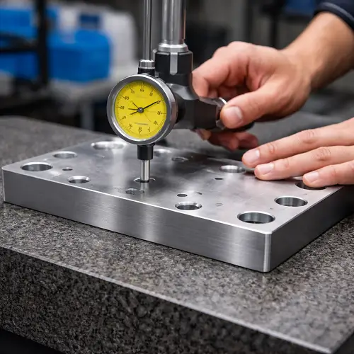
A dial indicator sweep gives a clearer picture of where the high and low regions are. This is especially useful when the part does not visibly rock but still shows poor seating behavior during assembly. The pattern of variation often tells whether the issue is a general bow, a twist, or a local high area.
CMM inspection becomes more useful when the face is large, the requirement is tight, or the customer needs a documented report. But even with higher-end inspection, the important question is still the same: does the measured variation actually reflect how the surface functions in the assembly?
Not every part needs the heaviest inspection method. Critical parts do need an honest one.
How Machine Shops Usually Control Flatness
A shop that is serious about flatness does not wait until final inspection to think about it. Most of the control comes from the process plan.
The first step is often leaving enough stock for finishing. If the critical face is taken to final condition too early, there is little opportunity left to correct movement later. A more stable approach is to rough the part, allow stress to settle if needed, then finish the critical surface once the part is closer to its final condition.
Balanced material removal is another big factor. When the process allows it, machining should avoid putting all the stress release on one side of the part. Even when perfect symmetry is not possible, the sequence can still be planned to reduce movement.
Fixturing also matters more than many people realize. A thin part that is over-clamped may look good during machining and fail after release. Better support, more even clamping, and less forced distortion usually help more than simply tightening the fixture harder.
On difficult parts, separating roughing and finishing can make a major difference. Some parts benefit from a rough cut, a pause, then a final finish pass after the geometry has settled. Shops do not need that for every job, but on critical flat faces it is often the difference between a stable part and a part that drifts after machining.
When requirements get especially tight, secondary finishing may become the practical solution. At that point, the conversation is no longer just about machining skill. It becomes a process selection issue.
What Usually Goes Wrong When Flatness Is Not Discussed Early
A common failure pattern looks like this: the drawing gives a general dimensional tolerance, the buyer assumes the main face will naturally be flat, and the shop machines the part using a normal strategy. The part comes out dimensionally acceptable, but assembly reveals rocking, uneven gasket contact, or unstable seating.
Another common problem appears on thin aluminum parts. The print may call for a very flat mounting face, but the geometry includes broad pocketing on one side and little structural support around the face. The requirement sounds simple on paper, but the part is naturally prone to movement. If nobody discusses that before production, the shop either struggles to hold the requirement or the part needs rework after inspection.
These are not unusual cases. They happen when flatness is treated like a minor note instead of a functional control.
When Flatness Should Be Called Out on the Drawing
A flatness callout should be used when the surface function depends on stable broad-area contact. Mounting faces, sealing faces, large locating faces, and reference faces for later assembly or machining are the most common examples.
It should not be applied everywhere by default. A non-critical exterior face, a surface that does not mate broadly with another part, or a face that has no real effect on sealing or stability usually does not benefit from an unnecessarily tight flatness requirement. Over-specifying flatness does not make the drawing more professional. It usually makes the part more expensive.
The best drawings separate critical surfaces from ordinary ones. That gives the shop a clear target and keeps process effort focused where it actually matters.
Why Tight Flatness Requirements Increase Cost
Tight flatness requirements make the process less forgiving. The shop may need more careful workholding, a slower cutting plan, more intermediate checking, or an additional finishing step. Inspection takes longer, and scrap risk goes up because the part has less room for natural movement.
This is why flatness should be tied to function. If the surface truly controls sealing, stability, or load transfer, then the tighter requirement may be justified. If the surface does not affect real performance, a severe requirement only adds cost without improving the part.
Practical Design Advice for Better Flatness Results
The easiest flatness problem to solve is the one that is addressed before the drawing is released.
Avoid unnecessarily large thin flat faces where possible. If one face is functionally critical, try not to combine it with extreme one-sided pocketing unless the design truly requires it. Separate critical functional faces from ordinary ones so the supplier knows where real control is needed. If a face is used for mounting or sealing, say so clearly rather than assuming the requirement is obvious from the model.
It also helps to discuss realistic expectations before production. A large thin aluminum plate and a compact steel block do not behave the same way. The same flatness value will not have the same manufacturing difficulty on both.
Conclusion
Flatness in CNC machining is not just a geometric definition. On real parts, flatness often decides whether a component sits correctly, seals correctly, and carries load the way the design intended. A part can pass dimensional inspection and still fail in use because the critical surface is not flat enough.
That is why flatness should be treated as a functional requirement, not just a print symbol. If a part includes a mounting face, sealing face, or broad mating surface, the real question is not only whether the dimensions can be machined. The real question is whether that surface can stay flat enough through fixturing, stock removal, unclamping, inspection, and assembly.
JeekRapid reviews this kind of part by looking at the material condition, stock removal pattern, setup method, and true function of the critical face before locking in the machining plan. For parts with important flat surfaces, send the drawing to JeekRapid early so the process route, inspection method, and realistic flatness requirement can be reviewed before production starts.
FAQs
What is flatness in CNC machining?
Flatness in CNC machining refers to how much a single surface can vary from a perfectly flat plane. It is used to control the form of a surface, especially when that surface affects mounting, sealing, or contact.
Why can a machined part meet size tolerance but still have flatness problems?
Because size tolerance controls dimensions, while flatness controls surface form. A part can have the correct thickness or profile and still carry a crown, hollow, or twist across the face.
What causes poor flatness in CNC machined parts?
Poor flatness is often caused by residual material stress, clamping distortion, uneven stock removal, thin-wall geometry, cutting heat, or unstable machining strategy.
How is flatness measured on machined parts?
Flatness can be checked with a surface plate and feeler gauge, a dial indicator sweep, or CMM inspection. The right method depends on how critical the surface is and how the part functions in assembly.
When should flatness be specified on a drawing?
Flatness should be specified when the surface affects mounting stability, sealing performance, or broad-area contact. It is usually not necessary on non-critical cosmetic or non-functional faces.