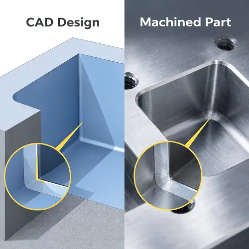
Sharp internal corners look clean in CAD. In real CNC machining, they are usually one of the first features that gets reviewed before a part is quoted or programmed. That is not because the machine cannot hold size. It is because standard milling tools are round, and round tools leave radius in inside corners.
This is a common source of confusion during RFQ review. A designer sends a model with square pockets, square internal edges, and tight mating features. On the screen, everything looks correct. Once the part is evaluated for machining, the real question is no longer whether the geometry looks right in CAD. The real question is whether those inside corners actually need to be sharp, how small the corner radius must be, and whether standard CNC milling is still the right process.
Some internal corners do matter. If a square insert has to sit fully into a machined pocket, an internal corner radius can stop assembly even when every nominal size on the print looks correct. The part may enter the pocket and still hang up at the corners. It may appear to fit but never seat flat against the bottom or locating faces. That kind of issue wastes time because the drawing looked acceptable, inspection may not catch the assembly condition clearly, and the problem only shows up once the parts are put together.
That is why sharp internal corners should be treated as a functional design topic, not just a geometric detail. A good supplier does not just say that a corner is hard to machine. A good supplier checks whether the corner is truly critical, what process risk it creates, and what design change or machining strategy will solve the problem without adding unnecessary cost.
What Are Sharp Internal Corners in CNC Machining?
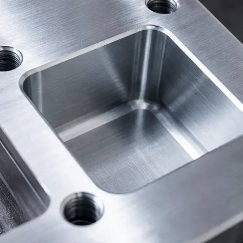
A sharp internal corner is an inside corner where two walls meet with little or no radius. In CAD, that usually appears as a clean 90-degree intersection. In actual CNC milling, that same corner almost always ends up with a radius because the cutter creating the feature has its own diameter.
This is one of the most basic but most misunderstood limits in machining. A milling machine can position a tool very accurately, but it still cannot make a cylindrical cutter produce a mathematically perfect zero-radius internal corner through ordinary milling alone. The geometry of the tool defines the geometry of the corner.
That is why internal corner radius matters even when it is not called out directly on the print. If a pocket is milled with an end mill, the inside corner keeps a fillet. The only real question is how large that fillet will be and whether the rest of the assembly can tolerate it.
Sharp internal corners show up in fixture plates, housings, mounting blocks, pockets for inserts, mold details, and many custom machined components. Some of those corners are just modeling defaults. Others directly affect fit, seating, or locating behavior. Separating those two cases is the first step in good DFM review.
Why Sharp Internal Corners Are Difficult to Machine
The first reason is tool shape. Standard end mills are round. When a round cutter moves into an internal corner, it leaves a curved intersection instead of a perfectly sharp one. This is not a machine accuracy problem. It is a physical result of the cutter geometry.
The second reason is tool rigidity. If a smaller internal corner radius is required, the shop usually has to move to a smaller end mill. Smaller tools are weaker, less rigid, and more sensitive to cutting load. As the tool diameter drops, deflection becomes more likely. That affects corner size, wall finish, repeatability, and in some cases even tool life.
The third reason is depth. A small internal radius in a shallow pocket may be manageable with a short cutter. The same corner radius at the bottom of a deep cavity is much more difficult. The tool must reach farther, which increases stick-out and reduces stiffness. At that point, the machining problem is no longer just about corner size. It becomes a combined problem involving access, vibration, chip evacuation, and stability.
Material also changes the situation. Aluminum is generally more forgiving than stainless steel or titanium. A small tool cutting a tight internal corner in aluminum may still be practical. The same feature in a harder or tougher material can push the tool close to its limit. Feed rate has to come down, the cut becomes more delicate, and the cost rises quickly.
This is why sharp internal corners often look simple to the customer and complicated to the shop. The corner itself may be small, but the process consequences are not.
What Controls Internal Corner Radius in CNC Machining?
The most direct factor is cutter diameter. In standard milling, the tool diameter largely controls the minimum radius left in an internal corner. A larger cutter leaves a larger radius. A smaller cutter leaves a smaller radius. That is the starting point for any internal corner discussion.
But real production decisions do not stop there. The actual practical corner radius is also shaped by feature depth, material, tolerance, and part quantity. A corner that is technically possible in a prototype may still be a poor choice for larger production runs if it forces an unstable tool strategy or long cycle times.
Pocket depth is one of the biggest hidden variables. Two parts may require the same internal corner radius on paper, but the deeper pocket will usually be harder to machine well. The deeper the cavity, the more tool reach is required. Once reach increases, rigidity drops. The result is a higher chance of deflection, chatter, or visible corner inconsistency.
Tolerance expectation matters too. Some customers care only that the mating part fits. Others want a small corner radius plus tight dimensional control plus clean corner finish. Those are not always compatible at the same cost level. A very small tool can chase the geometry, but the part may require more finishing passes and slower feeds to achieve the surface and dimensional quality the drawing implies.
This is why an experienced shop does not answer internal corner questions with one generic rule. The same radius request can be easy, borderline, or expensive depending on the rest of the part.
The Real Limits of Small Internal Corners
The real limit of a small internal corner is not whether a small cutter exists. The real limit is whether that cutter can do the job with enough stability and consistency to make sense for the project.
This is where many designs start to drift away from manufacturing reality. A CAD model may show a very tight internal corner and technically leave enough room for a small tool to enter. That does not automatically make the design practical. If the tool is too long, too fragile, or too slow for the material and part depth, the feature may still be a poor production decision.
In prototype work, a machine shop can sometimes accept that tradeoff. The part count is low, the time penalty is manageable, and the goal is often to get the geometry proven. In production, the same tradeoff may not hold. A corner that seemed acceptable on one or two parts may become expensive across dozens or hundreds of parts because the cycle time is too long or the tool wear becomes too high.
That distinction matters because customers often assume that “machinable” and “manufacturable” mean the same thing. They do not. A tight internal corner may be machinable in a controlled prototype environment and still be the wrong feature for routine production.
The practical limit is also tied to corner function. If a small corner radius is essential for assembly or locating, the effort may be justified. If the corner is simply a default CAD condition with no functional value, then pushing the process harder usually makes no sense.
When Sharp Internal Corners Matter in Part Design
Sharp internal corners matter when they affect how a part fits, seats, locates, or performs. That is the real dividing line. Many corners in CAD look sharp but do not control anything important once the part is actually used.
A common example is a square block or insert that has to fit into a milled pocket. The pocket dimensions may all look correct, but the part still does not seat because contact happens first at the corner radius. The insert may stop short of full depth, tilt slightly, or leave a visible gap against one face. In some cases, the part can even be forced in during assembly, only to create unwanted stress or difficult removal later.
This kind of issue is common in tooling plates, fixture details, stop blocks, locating features, and machined housings with rectangular components. It also shows up in mold work, where insert seating and corner definition can affect alignment or contact behavior.
Another case is where an inside corner acts as part of a locating system. If a component needs to register cleanly against two intersecting faces, excess radius in that corner may reduce seating accuracy or repeatability. That is more than a cosmetic concern. It becomes a function issue.
The mistake is assuming every inside corner belongs in that category. In many commercial parts, the corner does not guide, locate, seal, or seat anything. It only exists because nobody softened it in CAD. Those are the corners that should usually be opened up.
Problems Caused by Unnecessary Sharp Inside Corners
Unnecessary sharp internal corners add cost without improving performance. That is the most obvious problem, but not the only one.
They usually force the use of smaller cutters than the rest of the part would otherwise need. That leads to slower machining, more tool changes, and more local cleanup work. A large pocket may be easy to rough and finish with standard tooling, then suddenly require a secondary fine toolpath only because one non-critical corner was kept square in the model.
They also increase process risk. Small tools deflect more easily, especially in deeper features or harder materials. Once the tool is operating near its rigidity limit, surface finish can suffer, corner definition can vary, and tool life can drop. In extreme cases, the effort to keep a corner as small as possible causes more variation than a slightly larger and more stable radius would have produced.
Another issue is delay in DFM review. Parts with many square internal corners usually trigger questions before release because the shop has to determine which corners are critical and which are not. If the drawing or model does not make that clear, the RFQ slows down for a requirement that may not have mattered in the first place.
There is also the assembly trap. A customer may focus on nominal dimensions and miss the fact that the corner shape itself creates interference. The part looks correct on paper, passes basic size checks, and still does not assemble as expected. That kind of problem is much easier to avoid during design review than after machining.
Design Strategies That Make Internal Corners Easier to Machine
The best design strategy is to add radius anywhere the corner does not affect part function. This gives the shop more tool options, improves stability, and usually lowers machining time immediately. A realistic inside radius is often the simplest path to a better part.
Another good strategy is to review the mating component, not just the pocket. If a square-edged insert is driving the corner requirement, a small chamfer or edge break on the insert may solve the problem more efficiently than forcing the pocket into a very small internal radius. Many assemblies become easier to build once both parts are considered together instead of treating one part in isolation.
Local corner relief is another practical solution. Dog bone style relief or similar clearance features can allow a square part to sit properly in a milled pocket while keeping the main locating faces intact. This is especially useful in fixtures, housings, and interface features where face contact matters more than visual corner sharpness.
Selective control is also important. One corner may be critical while the rest of the part is not. The design should show that. When every internal corner is left equally sharp, the machine shop has to assume that all of them matter. That pushes the process toward the most difficult interpretation of the model.
It also helps to review depth early. A small corner radius at the top of an open feature may be entirely reasonable. The same radius at the bottom of a deep slot or cavity may require a very different approach. Internal corner design should always be reviewed together with reach and access, not just in plan view.
Common Design Mistakes With Sharp Internal Corners
One common mistake is leaving every inside corner perfectly square in CAD without asking whether the part actually needs it. This happens constantly in machined housings, plates, and pockets. The model looks neat, but the geometry creates machining work that serves no real function.
Another mistake is assuming that if the mating part is square, the receiving pocket must also be perfectly square. In many cases, a small edge break on the mating part or a local relief in the pocket is the more practical solution.
A third mistake is ignoring depth. Designers often focus on the top view of the part and choose a tight internal radius that looks manageable, then forget that the cutter has to reach the bottom of the feature. The corner may be simple on the screen and unstable in the machine.
There is also the mistake of carrying prototype logic directly into production. A part may be machined once with a very small tool and technically succeed, but that does not mean it is the right solution for repeat manufacturing. What works for a prototype does not always scale well.
Finally, many drawings fail to distinguish between critical and non-critical corners. That creates uncertainty during quoting and often leads to a slower or more conservative machining plan than the part really needed.
CNC Milling or EDM for Sharp Internal Corners
CNC milling is still the best process for most parts with internal corner features. It is faster, more economical, and usually sufficient once the design is adjusted realistically. Many sharp-corner concerns can be solved with proper corner radius, local relief, or a better understanding of what the assembly truly needs.
EDM becomes more attractive when the part genuinely requires near-square internal geometry or when the corner condition goes beyond what standard milling can produce efficiently. This is more common in tooling, hardened materials, mold details, or features where the internal corner itself is directly tied to function and cannot be relaxed.
That does not mean EDM is the automatic answer every time a CAD model shows a sharp corner. In many projects, EDM would add unnecessary cost and lead time because the part never truly needed that level of corner definition. The better answer is often hybrid manufacturing. Most of the geometry stays in CNC machining, while only the truly critical corner feature is handled by EDM or another secondary process.
This kind of split is often the most practical solution. It keeps the overall part cost under control while solving the specific area that ordinary milling cannot handle well. Good suppliers do not push everything toward EDM. They determine whether the corner is actually an EDM problem first.
How JeekRapid Solves Sharp Internal Corner Challenges
At JeekRapid, sharp internal corners are reviewed as part of the whole machining and assembly requirement, not as isolated geometric notes. The first question is whether the corner is actually functional. If the corner exists only because the CAD model was left square, the best solution is often to open the radius and keep the process simple.
If the corner does affect fit, JeekRapid reviews it together with pocket depth, cutter access, material, and tolerance requirements. That matters because the same corner request can behave very differently in aluminum, stainless steel, deep pockets, shallow cavities, prototypes, and production runs. Reviewing all of that together prevents the common mistake of approving a difficult corner based only on a top-view geometry check.
When a corner problem is really an assembly problem, JeekRapid can help identify that early. In many RFQ reviews, the inside corner itself is not the true issue. The real issue is a square mating feature with no relief, no chamfer, or no assembly clearance built into the design. In those cases, modifying the right feature is usually more effective than forcing the entire machined part into a tighter process.
When standard CNC milling is enough, JeekRapid can choose the most practical tool strategy for stable machining. When the feature starts pushing tool rigidity, cycle time, or repeatability too far, JeekRapid can recommend more realistic radius values, local relief, or a secondary process only where it truly adds value.
That review process gives customers something more useful than a simple yes or no. It gives them a part that is more likely to fit correctly, machine efficiently, and avoid unnecessary problems once production starts.
Before You Send a CAD File With Sharp Internal Corners
Before releasing a CAD file, it helps to review each sharp internal corner and decide whether it is truly functional. If the corner does not guide, locate, or support assembly, a realistic radius is usually the better choice.
It also helps to check the mating part. Many internal corner issues are really interface issues between two components. Looking at only one side of the fit can hide the real cause of interference.
Depth should be reviewed together with corner size. A tight radius in a shallow feature is very different from the same radius at the bottom of a deep pocket. This is one of the most common reasons a part looks easier in CAD than it does in machining.
Prototype and production intent should also be separated clearly. A feature that is acceptable for one-off machining may not be efficient for repeat manufacturing. That decision should be made before the process is locked in.
Most importantly, critical corners should be identified clearly. If only one or two corners on a part truly affect fit, that should be visible during DFM review. When the supplier knows which corners matter and which do not, the machining plan becomes faster, cleaner, and more cost-effective.
If the model includes square pockets, deep internal corners, or mating features that must fully seat, sending the file to JeekRapid before release can prevent unnecessary corner requirements, extra operations, and assembly issues later.
Conclusion
Sharp internal corners in CNC machining are not minor CAD details. They affect tool choice, corner radius, cycle time, stability, and in some cases whether the part will assemble correctly at all. Standard CNC milling naturally leaves radius in inside corners because the cutter is round. That is normal process behavior, not a machining defect.
The important question is not whether a sharp internal corner looks correct in the model. The important question is whether that corner is actually required for function. Some are. Many are not. Once that is understood, the part can be designed more intelligently, machined more efficiently, and assembled with fewer surprises.
For some projects, the right answer is a larger internal radius. For others, it may be local relief, a change to the mating feature, or a secondary process for one critical area only. The best result usually comes from early review, not from discovering the problem after the parts are already made.
If a part includes sharp internal corners, deep pockets, or square-fit features, sending the CAD file to JeekRapid before release is the right step. JeekRapid can review internal corner feasibility, process risk, and assembly intent, then recommend the most practical way to machine the part correctly the first time.
FAQs
Can CNC machining make perfectly sharp internal corners?
Standard CNC milling does not naturally create perfectly sharp internal corners because end mills are round. A small internal radius is usually left unless a secondary process is used.
Why do sharp internal corners cause assembly problems?
A square-edged part may contact the pocket radius first, which can stop the part from seating fully or create interference at the corner even when the basic dimensions look correct.
What controls internal corner radius in CNC machining?
Internal corner radius is mainly controlled by cutter diameter, but pocket depth, material, tolerance, and tool rigidity also affect what is practical.
When should EDM be used for sharp internal corners?
EDM is worth considering when the corner condition is truly critical and standard CNC milling cannot produce the required internal geometry efficiently or consistently.
How can designers make internal corners easier to machine?
Designers can add realistic radii, use local relief, modify mating part edges, and identify only the critical corners instead of leaving every inside corner perfectly sharp in CAD.