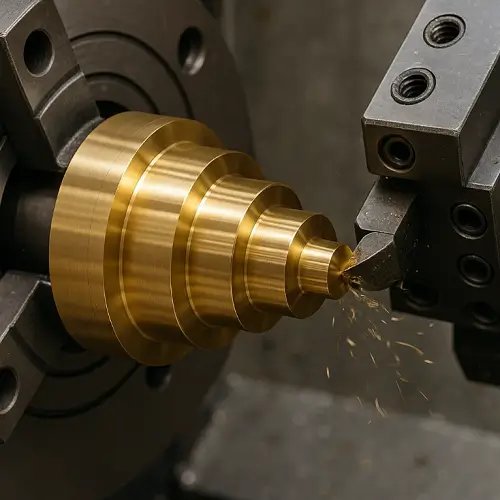
A hole and a shaft can look perfectly correct on a drawing and still turn into a bad assembly on the shop floor. One shaft stops halfway into the bore. Another part presses together, but the housing flares at the entrance. A third assembly works in raw machining and then becomes impossible after anodizing. That is why press-fit design in CNC parts should never be treated as a simple matter of nominal diameter.
A press fit is still a hole-and-shaft fit, but the difference between a fit that works and a fit that causes scrap usually comes down to more than size alone. Material pair, actual roundness, surface finish, coating buildup, wall thickness, and entry geometry all affect what happens when the parts meet under load. Anyone who has worked around production assemblies for a while has seen the same pattern: the print looks reasonable, the first sample seems acceptable, and the real problem only shows up when the parts are finished, repeated, and pressed in quantity.
What Is a Press Fit in Hole and Shaft Assembly?
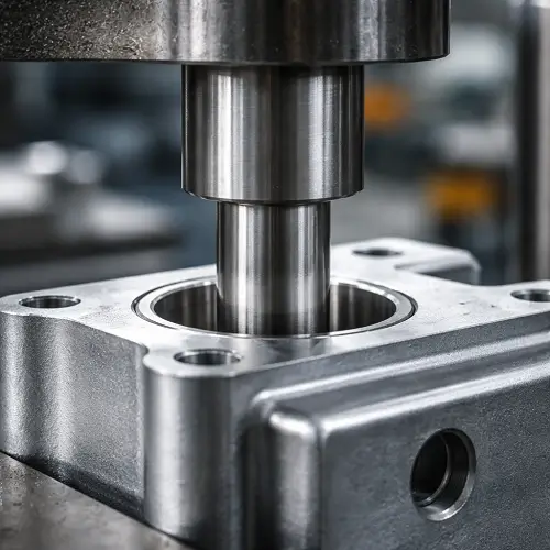
A press fit means the shaft is intentionally made slightly larger than the hole before assembly. In engineering language, that is an interference fit. Once the shaft is pressed into the bore, elastic deformation between the two parts creates holding force.
That makes a press fit different from a clearance fit, where the shaft slides into the hole freely, and different from a transition fit, where the parts may feel snug but do not always need real pressing force. In practical CNC work, press fits are used when a part needs to stay fixed in place without relying on a fastener, adhesive, or retaining ring.
The idea sounds simple. In real production, it rarely stays simple for long.
Why Hole and Shaft Fits Fail Even When the Drawing Looks Correct
Most failed press fits are not caused by one obvious mistake. They usually come from a stack of smaller problems that were never reviewed together.
The first issue is form. A hole can measure within tolerance and still be slightly tapered, lobed, or out of round. The shaft can also be nominally correct and still carry enough shape error to change the contact condition during pressing. A fit that looks fine when checked with a caliper can behave very differently once the shaft enters the bore.
The second issue is surface condition. A rough shaft does not contact the bore like a smooth cylinder. High surface peaks increase local pressure, raise insertion force, and make the assembly less repeatable. That is why two parts with the same nominal sizes can feel completely different in the press.
The third issue is edge condition. A missing chamfer, a light burr, or a damaged bore entrance can turn a workable fit into a part that jams in the first few millimeters. In many failed assemblies, the fit itself was not the only problem. The part was simply never given a proper lead-in.
The fourth issue is finishing. A shaft and hole may assemble correctly right after machining, then fail after anodizing, plating, or coating because the final dimensions are no longer the same as the machined dimensions.
How Much Interference Should a Press Fit Have?
This is usually the first thing a customer wants to know, and it should be answered directly.
There is no single interference value that works for every hole-and-shaft assembly, but there are reasonable starting points. For general CNC parts, light press fits often begin in the following range:
| Shaft Diameter | Practical Starting Interference | Notes |
|---|---|---|
| 3–6 mm | 0.005–0.015 mm | Use caution in aluminum and thin-wall parts |
| 6–12 mm | 0.010–0.025 mm | Common range for small machined assemblies |
| 12–25 mm | 0.015–0.040 mm | Check wall thickness and insertion length carefully |
These are starting points, not automatic release values.
A 0.015 mm interference may feel moderate in one steel assembly and far too aggressive in a thin anodized aluminum housing. Diameter matters, but so do material stiffness, contact length, wall support, finish quality, and assembly method. If the shaft is long, the wall is thin, or the fit has to survive coating buildup, the safe interference may be smaller than the chart suggests.
The mistake many teams make is assuming more interference always means a stronger joint. In reality, too much interference often brings a different set of problems: distorted bores, cracked housings, shaved material at the entry, higher runout after assembly, or a shaft that simply will not go in without excessive force.
Why Material Pair Matters in Press Fit Design
A steel shaft in a steel bore does not behave like a steel shaft in aluminum. Stainless in stainless behaves differently again. That is why copying one old fit value into a new design often creates trouble.
Steel-on-steel combinations usually hold geometry better once assembled, but the insertion force rises quickly as interference increases. If the surfaces are poor or lubrication is inconsistent, the risk of galling also goes up.
Steel into aluminum is more forgiving at the bore entrance in one sense, because aluminum yields more easily. At the same time, that softness creates new risk. The housing edge can deform, the bore can bell-mouth, and long-term holding force may relax more than expected if the surrounding structure is weak.
Stainless steel deserves extra caution. A fit that looks acceptable on paper can feel much tighter during assembly because friction is higher and the surface is less forgiving. If both parts are stainless and the fit is already aggressive, the assembly may become rough or unstable even before the nominal interference is reached.
The important point is simple: fit values should not be discussed without also discussing the material pair.
How Surface Finish Changes Hole and Shaft Fit Performance
Surface finish is not a cosmetic detail in press-fit work. It changes how the load is transferred between the shaft and the bore.
If the mating surfaces are too rough, contact happens first at the surface peaks. That increases local stress and makes insertion force less predictable. It also makes the fit more sensitive to tool wear and lot-to-lot variation. A shaft turned with a rougher finish can feel tighter than another shaft with the same measured diameter.
For many CNC press-fit features, keeping the mating surfaces around Ra 0.8 to 1.6 μm is a practical target when repeatability matters. Rougher finishes can still work in less demanding parts, but once the fit starts getting tight or the materials become softer, surface condition stops being a secondary issue.
This is one reason prototype assemblies sometimes give misleading confidence. One prototype may go together nicely because the operator happened to leave a smoother finish on the shaft. Production may feel different once tools wear, machines change, or another batch comes off a different setup.
How Anodizing and Coating Affect Press Fit Tolerance
This is one of the most common reasons a fit that worked at sample stage stops working in production.
The machined dimensions may be fine, but the finished dimensions are no longer the same part. Type II anodizing can add enough thickness to affect small bores and shafts. Hard anodizing has an even larger effect and can easily destroy the assembly margin on a small interference fit. The same problem shows up with plating and other coatings.
On small diameters, even a buildup measured in microns can be the difference between a clean press and a locked assembly. If that buildup was never included in the tolerance stack, the design may already be wrong before the first finished part leaves the line.
This is especially important on internal bores. Coating does not always grow in a perfectly uniform way, and deep or narrow features can behave differently from open surfaces. That means the final hole size may shift in a way that is harder to predict than many customers expect.
A very common shop-floor example looks like this: the raw-machined sample presses together with no drama, the customer approves the fit, production parts go through anodizing, and the first finished batch suddenly feels too tight. The operator presses harder, the bore edge starts to pick up material, and now the team is arguing about whether the problem came from machining, finishing, or assembly. In many cases, the real answer is simpler than that. The fit stack never fully accounted for the finish.
A Common Shop-Floor Case Customers Recognize Immediately
A realistic press-fit problem rarely begins with a dramatic failure. It usually starts with confusion.
A team may machine a small steel shaft and an aluminum housing, check the diameters, and see that both numbers are technically inside tolerance. The raw parts go together during the first try, maybe a little tight, but still acceptable. That early success creates confidence. Then the parts move into finishing. The housing gets anodized, the next batch comes back, and the same shaft that entered with a steady press before now stops at the mouth of the bore or drags badly halfway in.
At that moment, the customer often asks the same questions. Did the machine cut the hole undersize? Did the shaft come out oversized? Did the anodizing close up the bore? Did the operator press it crooked? In real production, the answer is often not one single mistake. It is the stack. A little coating growth, a little surface roughness, a little edge damage, and a little less support around the bore than the design really needed. That combination is exactly why press-fit problems feel confusing in the shop. Each variable looks small by itself, but together they change the whole assembly.
That is also why experienced suppliers do not review a press fit by looking at nominal diameters alone. They review the material pair, the finish, the wall thickness, the chamfers, and the final condition of the part, not just the raw machined size.
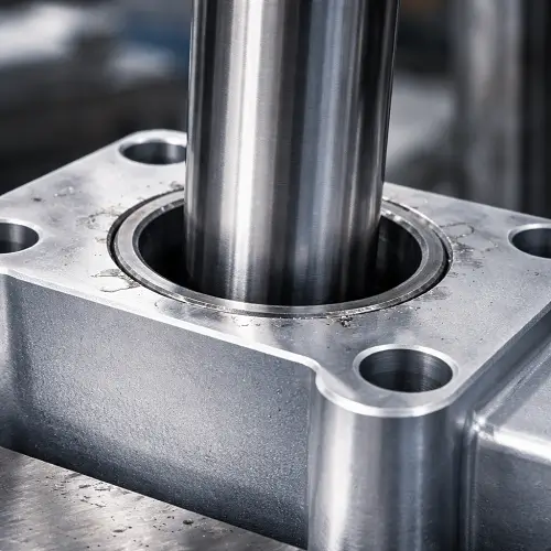
Why Thin Walls and Weak Geometry Make Press Fits Risky
A fit value that looks safe in a solid test block may be completely wrong in a real housing.
The surrounding material has to carry the stress created by the interference. If the bore sits inside a thin wall, close to an edge, near a slot, beside a thread, or inside a flexible bracket, the part may deform long before the nominal fit reaches full seating. The shaft may go in, but the bore can lose roundness, the edge can swell, and the part may no longer hold the geometry the assembly was supposed to protect.
This matters even more in aluminum. Thin aluminum around a press-fit bore gives less resistance to local distortion, so the entrance may flare and the bore may shift under load. A fit that seems light in a steel hub can become risky in a thin aluminum housing.
When the wall is weak, the correct move is usually not to keep increasing press force. The correct move is to review the design: reduce interference, strengthen the surrounding geometry, shorten the contact length, or change the retention method entirely.
Why Chamfers and Lead-In Features Matter in Assembly
Some press fits fail before the real fit even begins.
If the shaft edge is sharp and the bore mouth is sharp, the assembly starts by scraping material instead of guiding the parts together. That can shave the entry, roll up a burr, chip a coating, or push the shaft slightly off-axis before it has a chance to align. Once that happens, the rest of the press operation becomes harder than it should be.
A small lead-in chamfer often makes a noticeable difference. On many small machined parts, a chamfer around 0.2 to 0.5 mm is a sensible starting feature. Larger shafts and heavier fits usually need a more generous lead-in than that.
Chamfers do not fix a bad tolerance, but they make a good tolerance usable. Without them, even a well-designed fit can behave badly during real assembly.
Can CNC Machining Hold the Fit Consistently?
That depends on the feature, the material, and the actual process.
A simple external shaft is usually easier to control than a small deep bore. A short rigid feature is easier to hold than a thin sleeve or a long slender pin. A first-operation diameter is easier to control than a bore created after the part has already been clamped, released, and re-clamped.
This is where press-fit design often runs into production reality. A tolerance that looks reasonable in CAD may still be difficult to hold consistently if the bore is deep, the wall is thin, the tool is small, or the part moves after material removal. Even if the machine can hit the nominal size, the real question is whether it can hold size, form, and finish together across a full batch.
That is why fit reviews should never stop at “Can you make this diameter?” The better question is, “Can you hold this fit consistently in production, not just once on a good day?”
When a Press Fit Is the Wrong Choice
A press fit is useful, but it is not always the best answer.
If the part needs to be removed for service, a slip fit or light transition fit may be the smarter choice. If the wall around the bore is too thin, if the material is brittle, if coating buildup is hard to control, or if the assembly sits next to a bearing seat or sealing surface, forcing interference into the design may create more trouble than value.
There are many cases where another retention method works better. Adhesive retention, a shoulder with mechanical support, a retaining ring, a set screw, or a different fit class may give a more stable assembly with less risk of distortion or scrap.
A good design decision is not “use a press fit because press fits are strong.” A good design decision is “use a press fit only when the part, material, geometry, and process can actually support it.”
Conclusion
Press-fit tolerance is really a hole-and-shaft fit problem, but in CNC machining the fit that works is never defined by nominal size alone. Interference amount matters, but material pair, surface finish, roundness, coating buildup, wall stiffness, and entry geometry matter just as much. That is why one assembly presses smoothly while another locks up, galls, or distorts even though both drawings look acceptable.
The right question is not only what hole size and shaft size to use. The better question is whether the fit will still assemble after machining variation, surface condition, and finishing are included. That is what separates a fit that works in theory from one that works on the shop floor.
If a part includes anodizing, thin walls, small diameters, or a narrow assembly window, the fit should be reviewed before release. Send your drawings to JeekRapid to check hole-and-shaft tolerances, coating buildup, and realistic machining limits before production.
FAQ
1. What is the difference between a press fit and an interference fit?
In most machining discussions, they mean almost the same thing. Both describe a shaft that is intentionally larger than the hole before assembly. “Press fit” is the more common shop-floor term, while “interference fit” is the more formal engineering term.
2. How much interference should a press fit have?
There is no universal number, but light press fits on small CNC parts often begin around 0.005 to 0.015 mm for diameters near 3 to 6 mm, with larger diameters usually needing more. The final value should be based on material pair, wall thickness, insertion length, finish, and any coating applied after machining.
3. Does anodizing affect a press fit?
Yes. Even a relatively thin anodized layer can change a small bore or shaft enough to affect assembly force. That is why a fit that works in raw machining can become too tight after finishing if coating buildup was never included in the tolerance stack.
4. What surface finish is good for a press fit?
A smoother surface usually gives a more predictable result. For many CNC press-fit features, keeping the mating surfaces around Ra 0.8 to 1.6 μm is a good practical target when repeatability matters. Rougher surfaces can make the fit behave tighter than the nominal interference suggests.
5. When should a press fit be avoided?
A press fit should be reconsidered when the part needs repeated disassembly, when the housing wall is thin, when the material is brittle, or when coating buildup is hard to control. In those cases, a transition fit, slip fit, or another retention method often gives a more reliable result with less assembly risk.