Turbine blades sit at the center of modern turbomachinery. In aerospace engines, industrial gas turbines, and steam turbines, blade geometry directly governs thermal efficiency, mechanical reliability, and long-term service life. As operating temperatures and rotational speeds continue to rise, turbine blade manufacturing has become one of the most demanding disciplines in precision machining.
In real turbine production, the difficulty does not come from a single factor, but from the combined effect of high-temperature alloys, complex airfoil geometry, thin structural sections, and extremely tight accuracy requirements. Twisted airfoils, variable wall thickness, and strict surface integrity targets leave very little margin for process instability.
Under these conditions, 5-axis CNC machining is no longer an upgrade — it is the baseline requirement. Once blade geometry enters true airfoil form, conventional 3-axis strategies fail to control surface accuracy, stress distribution, and geometric stability at the same time.
This article explains how turbine blades are actually machined in production, and why 5-axis CNC remains the only practical solution for achieving stable airfoil accuracy.
What Is a Turbine Blade
A turbine blade is the primary working element that converts thermal and kinetic energy from high-temperature fluid flow into rotational mechanical power. In real turbomachinery systems, turbine blades operate under extreme conditions — continuous centrifugal loading, severe thermal gradients, high-cycle vibration, and aggressive oxidation — all while maintaining precise aerodynamic shape.
In aerospace engines, turbine blades routinely experience metal temperatures above 900–1100 °C, while industrial gas turbines impose long-duration thermal and mechanical loading that demands exceptional creep resistance and dimensional stability. Even minor deviations in blade geometry directly translate into measurable changes in engine efficiency, vibration behavior, and component life.
Unlike static structural components, turbine blades function simultaneously as aerodynamic surfaces and load-bearing mechanical elements. Their geometry must remain stable throughout the full operating envelope of the machine, making turbine blade manufacturing fundamentally different from most other CNC-machined parts.
Blade Structure & Function
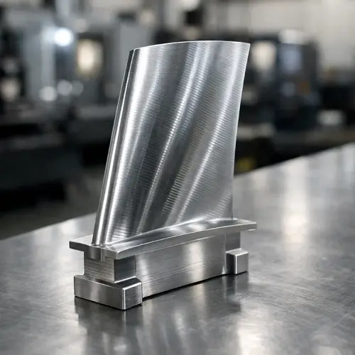
A typical turbine blade consists of several functional regions: the airfoil, which interacts with the working fluid; the platform, which seals the flow path; the root, which locks the blade into the rotor disk; and in some designs, the shroud, which controls leakage and vibration.
In simple terms, the root is the mechanical joint that secures the blade inside the rotating assembly.
Why 5-Axis CNC Is Required
Turbine blades feature continuously changing curved surfaces and extremely tight geometry requirements. Maintaining correct tool orientation across the airfoil is not possible using fixed-axis machining.
In most turbine blade programs, airfoil profile control is typically held around ±0.02 mm, and once geometry moves beyond that range, vibration and efficiency loss become visible at the system level. 5-axis machining maintains stable cutting forces and consistent surface quality across the entire blade.
Many of the same geometric and process constraints appear in blisk machining for aerospace engines, where the blades and disk are produced as a single structure.
In that case, cumulative error, thermal distortion, and blade-to-blade consistency become even more difficult to control because no mechanical separation exists between components.
Turbine Blade Machining Process
CAD/CAM Design
Before any metal is cut, the entire process is defined inside the CAD/CAM system. Engineers build the complete 3D blade model, including airfoil geometry, structural features, and fixturing references. In the CAM environment, 5-axis toolpaths, cutting strategies, and process sequencing are established.
For turbine blade machining, CAD/CAM is not merely programming — it defines cutting stability, tool engagement, and thin-wall control for the entire manufacturing cycle.
Material Selection
Material choice directly affects the stability of every downstream operation. Most turbine blades are produced from high-temperature alloys such as Inconel or titanium. These materials maintain strength at elevated temperature but exhibit low thermal conductivity and high cutting resistance.
An improper material-process match leads to excessive tool wear, heat concentration, and surface damage during rough machining, problems that cannot be fully corrected later in finishing.
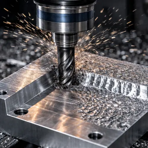
Rough Machining
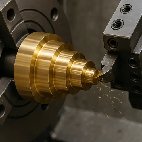
Machining begins by establishing stable geometry. The root region is typically machined first to create a reliable reference for fixturing and alignment. The platform follows, removing non-functional material and balancing the overall structure. The airfoil then undergoes controlled bulk material removal using 5-axis motion, preserving uniform stock for finishing while keeping cutting forces stable.
Semi-Finishing
Semi-finishing gradually refines the airfoil contour and stabilizes thin-wall sections. This stage allows internal stress to release progressively, preventing distortion during final machining and maintaining geometric control.
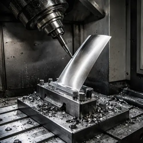
Final Finishing
Final finishing defines aerodynamic accuracy. Toolpaths follow airflow direction, controlling leading-edge thickness and curvature continuity. In practice, leading-edge thickness is often controlled within ±0.01–0.02 mm, because anything larger starts to appear as measurable airflow disturbance.
Deburring & Edge Conditioning
After finishing, micro-burrs remain at critical locations such as the leading edge, trailing edge, and platform transitions. Even very small burrs above 0.02 mm at the trailing edge can become fatigue initiation points in high-speed operation, so edges are lightly conditioned while preserving aerodynamic form.
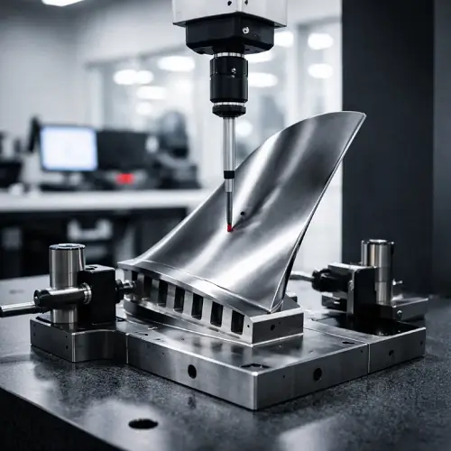
Inspection
Final verification uses CMM measurement and surface scanning to evaluate airfoil shape, thickness distribution, root geometry, and blade twist. For most programs, overall airfoil deviation staying within ±0.02 mm is considered the baseline acceptance level.
Types of Turbine Blades
Impulse Turbine Blades
Impulse turbine blades extract energy primarily from the momentum of high-velocity fluid jets rather than from a pressure drop across the blade. The incoming flow is shaped by nozzles and directed at the blade at very high speed, and the blade geometry is optimized to redirect the jet with minimal energy loss. These blades are commonly used in steam turbines and certain high-speed industrial turbines, where stable jet interaction and precise surface finish play a major role in efficiency, vibration behavior, and erosion resistance.
Reaction Turbine Blades
Reaction turbine blades operate by combining fluid momentum with a pressure difference across the airfoil. The blade cross-section closely resembles an aircraft wing, and the aerodynamic profile must remain extremely stable to maintain efficiency and load balance across the rotor stage. Reaction blades dominate modern gas turbines and aero engines, where blade geometry accuracy directly affects thermal efficiency, cooling effectiveness, and overall engine performance.
Shrouded Turbine Blades
Shrouded turbine blades include an additional structural feature at the blade tip that interlocks with neighboring blades. The shroud reduces tip leakage, improves aerodynamic efficiency, and adds mechanical damping to control vibration. From a manufacturing perspective, shrouded blades introduce significant machining complexity because the airfoil, shroud, and interlocking features must all be produced with tight tolerances while maintaining structural integrity.
Unshrouded Turbine Blades
Unshrouded turbine blades operate without a tip shroud and rely entirely on extremely tight clearance control between the blade tip and the turbine casing. This design reduces rotating mass and improves dynamic response, making it common in high-speed aerospace turbines. However, it places extreme demands on airfoil accuracy, surface integrity, and long-term dimensional stability during manufacturing.
Aerospace Turbine Blades
Aerospace turbine blades are designed to withstand the most severe operating conditions, including extreme temperatures, high rotational speeds, and intense vibration. These blades typically incorporate complex internal cooling passages, thin airfoil walls, and advanced superalloys or single-crystal materials. Manufacturing aerospace turbine blades represents the highest level of difficulty in turbine blade machining, with exceptionally tight control required over geometry, surface quality, and material integrity.
Industrial Power Turbine Blades
Industrial power turbine blades are optimized for continuous, long-duration operation in power generation environments. Compared with aerospace blades, they allow slightly heavier sections but demand outstanding resistance to creep, corrosion, and thermal fatigue. Their manufacturing focus is on long-term stability, predictable performance, and minimal maintenance over extended service cycles.
Relationship to Impeller Machining
From a manufacturing perspective, turbine blade machining and impeller machining belong to the same family of high-precision 5-axis curved-surface production. Both depend on identical principles of fixture stability, toolpath control, surface integrity management, and inspection discipline.
For engineers working with complex rotating components, impeller machining provides a valuable technical reference for understanding turbine blade production challenges.
Ready to Machine Turbine Blades with JeekRapid?
Turbine blade machining is not just about reaching dimensional tolerance on a drawing. It is about controlling geometry, surface integrity, and long-term stability across the entire manufacturing cycle, under some of the most demanding operating conditions in modern engineering.
From CAD/CAM strategy and material behavior to 5-axis toolpath control, thin-wall stability, and final inspection, every step of the process influences blade performance and service life. Successful turbine blade production requires both advanced equipment and deep process understanding.
If your project involves complex airfoil geometry, tight tolerance requirements, or high-temperature materials, JeekRapid is prepared to support turbine blade machining from prototype through production.
Drawings and technical data can be submitted for engineering review and manufacturability feedback before cutting begins.