In real production, impellers almost always require 5-axis CNC machining. This is not a matter of machine preference or equipment marketing. The reason is straightforward: the hydraulic performance of an impeller is controlled by blade geometry, hub alignment, and the consistency of the flow surfaces, and these features cannot be held reliably with simple 3-axis motion. When any of these geometric relationships drift, efficiency drops, vibration increases, and service life shortens.
Most impeller problems seen on the shop floor are not caused by material defects but by geometric instability introduced during machining.If an impeller shows vibration during its first test run, the root cause is usually not the material, but the geometry created upstream in machining. Distorted blade profiles, uneven surface finish, poor hub concentricity, and imbalance after finishing are the most common failure sources. Once these appear, correcting the part becomes expensive or impossible. This is why stable impeller production is built around continuous 5-axis toolpaths, controlled surface transitions, and strict verification of both geometry and balance.Many of the same geometric and process challenges appear in turbine blade machining, where airfoil accuracy, thin-wall stability, and surface integrity dominate production risk in high-speed rotating components.
What Is an Impeller
An impeller is a rotating mechanical component that transfers energy from a motor or turbine into a fluid. As the impeller rotates, the blades accelerate the fluid outward, converting mechanical energy into pressure and flow. This energy conversion process defines the performance of pumps, compressors, and turbomachinery systems.
From a machining perspective, an impeller is not simply a round part with blades attached. The blade curvature, blade thickness, inlet and outlet angles, hub geometry, and surface quality work together as a single functional system. Small deviations in blade form or surface condition can create measurable changes in flow behavior, noise, and efficiency. For this reason, impeller machining is fundamentally a problem of precise geometry control rather than basic material removal.
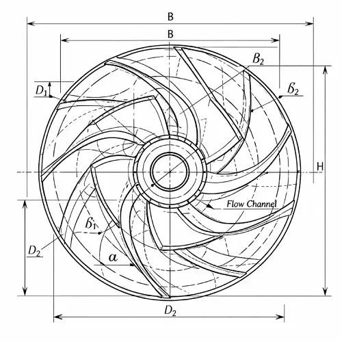
Main Components of an Impeller
An impeller is composed of several critical functional features that must work together as a balanced rotating system. From a machining standpoint, the most important components include the hub, the blades, the shroud (for closed designs), the bore and drive interface, and the rear face where balance features are often applied. Each of these elements introduces its own machining challenges, and errors in any one area directly affect the performance of the entire assembly.
Hub and Structural Core
The hub forms the structural core of the impeller. It connects the impeller to the shaft and carries the primary mechanical load. Machining of the hub demands tight control of concentricity, bore geometry, and face runout. Any misalignment between the hub bore and the blade geometry will appear as vibration during operation and accelerate bearing wear in the final assembly.
Blades and Flow Surfaces
The blades are the most sensitive and technically demanding surfaces of the part. Blade thickness, camber, inlet and outlet angles, and surface continuity determine how energy is transferred into the fluid. From a machining perspective, the blades require continuous, smooth tool motion to maintain consistent curvature and surface finish. Even small toolpath discontinuities can introduce flow disturbances that reduce efficiency and increase noise.
Shroud and Flow Channel Control
In closed and semi-closed impeller designs, the shroud encloses the blade tips and forms the final flow channel. The shroud-to-blade relationship must be controlled carefully, particularly at the leading and trailing edges where clearance and surface transitions influence leakage and hydraulic losses. Machining distortion or residual stress in this region often shows up later as imbalance or premature failure.
Bore and Drive Interface
The bore, keyway, or spline features provide torque transmission between the impeller and the shaft. These features must be machined with precise positional accuracy relative to the blade geometry. If the drive interface is not concentric with the aerodynamic center of the blades, dynamic imbalance becomes difficult to correct during balancing.
Rear Face and Balance Features
The rear face of the impeller typically contains balance pads or correction features used during dynamic balancing. Machining this surface flat and stable is essential for accurate balancing results. Poor surface integrity here limits how precisely imbalance can be corrected and may require excessive material removal that weakens the structure.
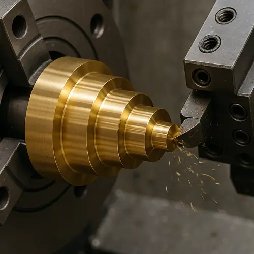
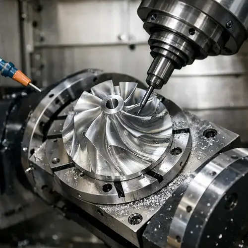
Why Impellers Require 5-Axis Machining
Impeller geometry cannot be manufactured reliably with simple 3-axis motion. The blade surfaces are fully three-dimensional, continuously curved, and tightly integrated with the hub and shroud. Any attempt to machine these features with multiple 3-axis setups introduces positional error, surface discontinuity, and cumulative tolerance stack-up that quickly exceeds functional limits.If this sounds familiar from past projects, it is because nearly every impeller program runs into this exact wall.
Continuous Blade Surface Control
With 5-axis machining, the cutting tool remains continuously normal to the blade surface, allowing smooth surface transitions and consistent chip load across the entire blade profile. This single capability eliminates most of the form error that appears in repositioned 3-axis operations and dramatically improves surface finish and dimensional repeatability.
Critical Blade-to-Hub Transitions
Blade-to-hub transitions are one of the most sensitive regions on an impeller. This fillet zone carries high mechanical stress and strongly influences flow behavior. 5-axis control allows this region to be machined in one continuous motion, preserving surface integrity and avoiding the step lines that are common in indexed machining strategies.
Shroud and Internal Flow Channel Constraints
Closed and semi-closed impellers introduce additional constraints. The presence of the shroud restricts tool access and forces simultaneous multi-axis motion to maintain correct lead angle and tool orientation inside the flow channel. Without 5-axis capability, these internal blade surfaces cannot be reached without excessive tool overhang, vibration, and loss of surface control.
Balance Consistency and Geometric Symmetry
Equally important, 5-axis machining improves mass symmetry and balance consistency. Because the entire blade system is produced in a single coordinated setup, geometric deviations between blades are minimized. This reduces the amount of correction required during dynamic balancing and improves long-term operating stability.These same 5-axis control constraints become even more restrictive in blisk machining for aerospace engines, where blades and disk are produced as one integrated structure and cumulative error cannot be isolated through assembly.
Types of Impellers from a Machining Perspective
From a machining standpoint, impellers are commonly classified into three main types: open impellers, semi-open impellers, and closed impellers. Although these designs serve similar hydraulic functions, their machining requirements and risk profiles differ significantly.
Open Impellers
Open impellers have blades attached directly to the hub without a front shroud. This structure provides the best tool access and the simplest machining conditions. Blade surfaces are fully exposed, making roughing and finishing relatively straightforward with 5-axis control. However, because there is no shroud to stabilize the blade tips, blade thickness and edge consistency must be controlled carefully to prevent deformation during cutting and service.
Semi-Open Impellers
Semi-open impellers include a partial shroud on one side of the blade set. This design improves structural stiffness and flow stability compared to open impellers, but it also introduces restricted tool access along the blade tips. Maintaining consistent blade clearance and surface finish in these partially enclosed regions requires precise tool orientation and careful management of tool deflection and vibration.
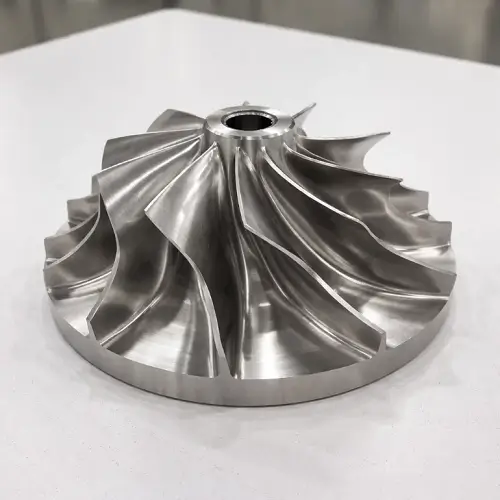
Closed Impellers
Closed impellers feature full front and rear shrouds that enclose the blades and form a complete flow channel. This design offers the highest hydraulic efficiency but also presents the most demanding machining challenge. Tool access is severely limited, internal surfaces must be machined with long-reach tooling, and maintaining surface integrity inside the flow channel requires fully coordinated 5-axis motion. Even small geometric errors in closed impellers can create significant performance losses and balancing difficulties.
Typical Impeller Machining Process
Impeller machining begins long before the first chip is cut. The process is driven by geometry control, not simply by material removal. Every step is organized to protect blade form, surface integrity, and balance from the earliest roughing stage through final inspection.
Design Review and CAM Strategy
The process starts with a detailed review of the impeller model and functional requirements. Blade geometry, flow surfaces, hub alignment, and tolerance zones are analyzed before any toolpaths are created. CAM programming focuses on maintaining continuous surface motion, stable cutter engagement, and minimizing repositioning. For most impellers, a full 5-axis strategy is established at this stage to avoid later geometric correction.
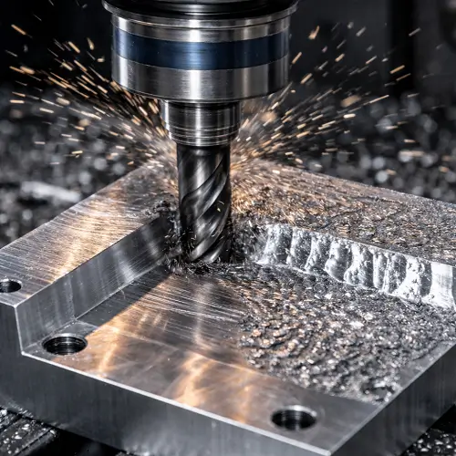
Rough Machining
Roughing removes the bulk of the material while maintaining structural stability of the blank. Cutting forces are carefully balanced to prevent blade distortion and residual stress. Tool engagement is managed to avoid excessive heat buildup, particularly in thin blade sections where thermal expansion can compromise geometry.
Semi-Finishing
Semi-finishing establishes the near-net blade form and hub geometry. This stage is critical for controlling material stress and preparing the surfaces for final finishing. Any deviation introduced here will propagate into the finishing stage, making correction difficult without overcutting critical features.
Blade Finishing
Blade finishing defines the final aerodynamic surfaces. Continuous 5-axis motion is used to maintain consistent surface contact and uniform cutter loading. Surface finish, edge integrity, and blade thickness are controlled simultaneously. Toolpath smoothness at this stage has a direct impact on hydraulic performance.
Hub and Bore Finishing
The hub bore, faces, and drive features are finished after blade geometry is stabilized. Concentricity between the bore and the blade system is tightly controlled. This alignment governs vibration behavior and determines how effectively the impeller can be balanced.
Deburring and Edge Conditioning
All sharp edges and micro-burrs are removed without disturbing the blade profile. Improper deburring at this stage can alter flow characteristics and introduce localized stress concentrations.
Dynamic Balancing
The impeller is dynamically balanced to achieve the specified balance grade. Because the blade geometry has been preserved throughout machining, minimal material correction is normally required. Excessive correction indicates earlier geometric instability in the machining process.In practice, when balancing starts to consume significant time, the machining process almost always needs to be reviewed rather than the balancing procedure itself.
Final Inspection
CMM inspection verifies blade profiles, hub alignment, bore concentricity, and critical surface dimensions. Surface roughness is measured on key flow regions. Only after geometry and balance are confirmed is the impeller released for assembly or shipment.
Materials Commonly Used for Impeller Machining
Material selection for impellers is driven by operating environment, mechanical load, corrosion exposure, and required service life. Each material introduces different machining behavior, cutting stability, and surface integrity challenges, which directly influence process planning and cost.
Aluminum Alloys
Aluminum is widely used for impellers in lightweight, high-speed, and low-load applications. It offers excellent machinability, allowing fine surface finishes and tight tolerances with relatively high material removal rates. However, thin aluminum blades are prone to vibration and deflection, requiring careful toolpath design and controlled cutting forces to maintain blade geometry.
Stainless Steel
Stainless steels are selected for corrosion resistance and mechanical strength in demanding fluid environments. Machining stainless impellers requires stable cutting conditions, rigid fixturing, and precise thermal control. Work hardening and tool wear must be managed carefully, especially along blade edges and in closed impeller channels where tool access is restricted.
Titanium Alloys
Titanium impellers are used in aerospace, high-performance compressors, and chemically aggressive environments. The low thermal conductivity and high strength of titanium increase cutting temperatures and tool wear. Achieving stable surface finish and dimensional control demands conservative cutting parameters and optimized 5-axis toolpaths.
Nickel-Based Superalloys
Materials such as Inconel are applied where high temperature and extreme mechanical loads are present. These alloys are among the most difficult materials to machine. Cutting forces, heat management, and tool life control become dominant process factors. Maintaining blade accuracy under these conditions requires highly rigid machine platforms and precise process monitoring.
Bronze and Brass
Bronze and brass impellers are common in marine and chemical service applications. These materials machine smoothly and allow good surface quality, but care must be taken to avoid built-up edge and maintain sharp cutting edges on fine blade features.
Impeller Machining Tolerances and Surface Finish
Impeller performance is extremely sensitive to geometric accuracy and surface condition. Tolerances and surface finish are not cosmetic specifications; they directly affect hydraulic efficiency, vibration behavior, noise level, and service life.
Blade Profile and Form Accuracy
Blade profiles must be controlled within tight form tolerances. In most precision impeller applications, blade profile accuracy is typically held within ±0.01 mm, with tighter requirements applied to high-speed or high-efficiency designs.
Hub Concentricity and Bore Alignment
Bore concentricity and face runout are commonly controlled within 0.005–0.01 mm. Poor alignment in this area manifests as vibration during operation and places unnecessary load on bearings and seals.
Surface Finish of Flow Channels
Typical hydraulic surfaces are finished to Ra 0.8 μm or better, with high-performance designs often requiring Ra 0.4 μm or lower.
Dynamic Balance Requirements
Finished impellers are dynamically balanced to grades ranging from G2.5 to G6.3, depending on application.
Thermal and Residual Stress Control
Residual stress introduced during machining is minimized through controlled cutting strategies and proper sequencing to preserve long-term dimensional stability.
3-Axis vs 5-Axis Impeller Machining
From a purely theoretical standpoint, an impeller can be machined on a 3-axis machine. In practical production, however, the quality, consistency, and efficiency of the final part depend heavily on 5-axis capability.
Geometry Control and Surface Quality
3-axis machining relies on multiple setups and indexed positioning to reach complex blade surfaces. Each reposition introduces alignment error and surface discontinuity, which accumulates across the blade system. These small errors may appear acceptable individually but combine to create measurable imbalance, reduced hydraulic efficiency, and inconsistent surface finish.
5-axis machining maintains continuous tool orientation normal to the blade surface. This allows smooth transitions across the entire blade profile, consistent chip load, and uniform surface quality without interruption. The result is significantly higher form accuracy and repeatability.
Tool Access and Stability
In closed and semi-closed impeller designs, tool access becomes severely restricted. With 3-axis strategies, long tool overhang and shallow approach angles are often unavoidable, leading to vibration, deflection, and poor surface control.
5-axis motion allows the cutting tool to approach the surface from optimal angles, reducing tool length, improving rigidity, and maintaining stable cutting conditions even deep inside flow channels.
Setup Count and Error Accumulation
A typical 3-axis impeller process may require four or more separate setups. Each setup introduces new fixturing error and increases the risk of cumulative tolerance drift.
5-axis machining consolidates most of the operation into a single coordinated setup. This drastically reduces positional error, improves concentricity between features, and simplifies quality control.
Overall Production Efficiency
While 3-axis machining may appear less expensive at the machine-hour level, the total production cost of a precision impeller is usually lower with 5-axis machining due to reduced setups, less rework, fewer scrap parts, and more consistent balancing results.
Common Impeller Machining Problems and Solutions
Blade Surface Distortion
Thin impeller blades are highly sensitive to cutting forces and residual stress, something most production teams discover the hard way on their first few impeller programs. Excessive material removal in a single pass or poor sequencing between roughing and finishing can distort blade profiles. This distortion often appears after part release and becomes impossible to correct without re-machining critical surfaces.
Stable roughing strategies, controlled step-down, and staged semi-finishing are used to minimize stress accumulation and preserve blade geometry.
Inconsistent Surface Finish on Blades
Vibration, tool wear, and improper tool orientation frequently create uneven surface finish across blade surfaces. In hydraulic components, these variations increase friction losses and disturb flow.
Continuous 5-axis toolpaths, reduced tool overhang, and consistent cutter engagement are essential to maintaining uniform surface quality.
Hub and Bore Misalignment
Misalignment between the hub bore and blade geometry leads directly to vibration and short bearing life. This issue is often caused by multiple setups and accumulated positioning error.
Consolidating operations into a single 5-axis setup and performing critical bore finishing after blade geometry is stabilized helps maintain concentricity.
Balancing Difficulties
Excessive balancing correction is usually a symptom of upstream geometric instability. When blade symmetry is not controlled during machining, large correction masses must be removed, weakening the structure.
Proper 5-axis machining combined with strict blade form control reduces balancing effort and improves long-term stability.
Applications of Impeller Machining
Impellers are core components in a wide range of fluid and energy systems. The machining requirements vary by industry, but the underlying technical challenges remain consistent: geometry control, surface integrity, and long-term stability.
In pump systems, impeller accuracy directly affects flow rate, efficiency, cavitation behavior, and operating noise. Industrial process pumps, chemical pumps, and water circulation systems all rely on precise blade geometry and stable balance to maintain performance over long service cycles.
In compressors and turbomachinery, impellers operate at high rotational speeds under significant thermal and mechanical load. Small geometric deviations become magnified at operating speed, making blade profile control and hub concentricity critical to reliability and fatigue life.
In aerospace and high-performance energy systems, impellers are subjected to extreme operating environments. Materials such as titanium and nickel-based alloys are common, and machining must meet stringent tolerance and surface finish requirements to ensure structural integrity and aerodynamic performance.
Why Engineers Choose JeekRapid for Impeller Machining
Engineers select JeekRapid for impeller machining projects because stable geometry control is built into the manufacturing process, not added later through correction. Every impeller program begins with a detailed review of blade geometry, tolerance requirements, and functional surfaces before CAM development. Continuous 5-axis machining strategies are applied to preserve blade form, minimize residual stress, and maintain consistent surface quality across the entire flow channel.
JeekRapid focuses on minimizing error sources rather than correcting them after machining. By consolidating operations into coordinated 5-axis setups, controlling tool engagement, and sequencing material removal carefully, blade symmetry and hub alignment remain stable throughout production. This approach reduces balancing correction, shortens development cycles, and improves long-term operating reliability.
Ready to get a parts quote? Submit your CAD file now.
FAQs
What tolerance levels are typical for precision impeller machining?
Most high-performance impellers require blade profile accuracy within ±0.01 mm and bore concentricity within 0.005–0.01 mm, depending on operating speed and application.
Can closed impellers be machined without 5-axis CNC?
Closed impellers can be produced with indexed 3-axis machining, but maintaining consistent blade geometry, surface finish, and balance becomes extremely difficult. 5-axis machining is the standard solution for reliable production.
Which materials are most difficult for impeller machining?
Titanium and nickel-based superalloys present the greatest challenges due to high cutting forces, thermal effects, and tool wear, especially in closed impeller designs.
How is impeller balance controlled during machining?
Stable blade geometry and hub alignment produced during machining minimize imbalance. Final dynamic balancing corrects only minor residual mass deviations.