A part may pass inspection during the first run and still begin to show variation after several batches. Hole locations shift slightly. Flatness becomes harder to control. Assemblies that once fit easily start to require adjustment, even though the program, tooling, and operators remain unchanged.
Initial responses usually focus on feeds, offsets, or tooling. Toolpaths are adjusted. Cutting parameters are softened. These changes may stabilize the process briefly, but the underlying behavior often returns.
What eventually becomes clear is that the machine itself defines how stable the process can be once material is being removed. CNC machine selection sets the baseline accuracy window long before fine adjustments come into play.
Does CNC Machine Type Affect Part Accuracy?
In most CNC machining environments, achievable accuracy falls into a few practical ranges that show up repeatedly in real production.
General production accuracy
Around ±0.002–0.003 in
Common for standard machining centers running everyday work.
At this level, parts generally assemble without issue, and minor variation does not affect function. Most commercial and industrial components fall into this category.
Tight-tolerance machining
Around ±0.001 in
Requires a rigid machine, controlled setups, and a stable process.
Here, parts may still look “normal” to the eye, but small variations start to matter. Machine stiffness, setup consistency, and thermal behavior become critical.
High-precision machining
Around ±0.0005 in
Usually limited to well-maintained machines, short tool reach, and careful thermal control.
At this point, the process window narrows significantly. Small changes in temperature or cutting conditions can push features out of tolerance.
Ultra-precision work
Below ±0.0002 in
Typically outside normal CNC milling and more common in grinding, jig boring, or dedicated precision equipment.
Different CNC machine types naturally operate in different parts of this spectrum. Machine selection matters because it defines which of these accuracy bands can be held consistently, not just once during inspection.
How Accurate Is a 3-Axis CNC Machine in Practice?
For parts that can be completed in one or two controlled setups, a rigid 3-axis machining center can reliably operate in the ±0.001 in range on critical features. Flatness and perpendicularity are often easier to manage because fewer axes are moving and fewer mechanical elements are involved.
Once additional setups are required, alignment variation begins to accumulate. Each re-clamping introduces small positional changes. Individually, these shifts may be difficult to detect. Across multiple setups, their combined effect becomes visible in inspection results.
This is why many tight-tolerance production parts continue to run on high-quality 3-axis machines. When geometry allows, fewer variables translate into better repeatability.
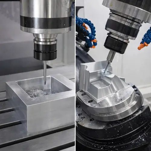
Is a 5-Axis CNC Machine More Accurate Than a 3-Axis Machine?
Reducing the number of setups changes how error accumulates. Completing a part in a single clamping removes a major source of positional variation, particularly for features that must relate to each other.
At the same time, additional axes introduce their own behavior. Rotary axes have different stiffness characteristics, thermal response, and positioning behavior than linear axes. If these axes are not well calibrated or mechanically stable, they introduce variation that offsets the benefit of fewer setups.
Whether accuracy improves depends on how these factors balance in real cutting conditions. A well-maintained 5-axis machine can significantly reduce accumulated error. A poorly tuned one may struggle to match the consistency of a simpler, more rigid 3-axis setup.
What Limits CNC Machining Accuracy?
As cutting continues, small physical effects compound. Inspection results begin to spread. Assemblies feel less predictable. Adjustments become more frequent.
At this point, further changes to offsets or cutting parameters yield diminishing returns. The limiting factors are no longer in the program, but in how the machine behaves under load.
CNC machining accuracy is constrained by mechanical reality. Cutting forces, heat, stiffness, vibration, and wear interact continuously during operation. These interactions define what the process can maintain over time.
Machine Rigidity
When rigidity is insufficient, deflection appears as feature-to-feature variation rather than obvious size errors. A single dimension may measure correctly while positional relationships degrade across the part.
As cutting forces increase or tool reach extends, deflection grows. Tool wear amplifies the effect, even if cutting parameters remain unchanged. Machines with higher structural stiffness limit this movement and maintain geometry more effectively across multiple features.
Structural Vibration and Damping
Vibration influences surface finish, tool life, and dimensional stability. Poor damping allows cutting forces to excite the machine structure.
As vibration increases, surface quality degrades and dimensional variation grows. Machines with well-designed structures absorb and dissipate vibration more effectively, particularly when machining harder materials or using extended tooling.
Thermal Stability
Thermal expansion influences geometry as machines warm during operation. Small dimensional shifts accumulate as internal temperatures change.
Parts may meet tolerance early in a run and drift later, even when tooling and programs remain unchanged. Machines designed with better thermal balance tend to stabilize after warm-up, while others continue to move as conditions change.
Tolerance Stack-Up Effects
Tolerance stack-up becomes a real issue once a part includes multiple features or requires more than one setup.
Individual dimensions may all meet size tolerance, yet small variations accumulate across features. Hole diameter, slot width, and thickness can look perfect on inspection, while feature-to-feature relationships drift enough to cause assembly problems.This is often discovered during assembly, when parts that pass inspection still require force, shimming, or rework to fit together.
In multi-setup machining, tolerance stack-up is strongly influenced by datum selection. When reference surfaces change between setups, even a process holding ±0.001 in on individual features can produce significantly larger positional variation after re-clamping.
This is why size accuracy and positional accuracy behave differently. Size errors are often corrected with tool offsets. Errors caused by tolerance stack-up affect feature location, perpendicularity, concentricity, and true position, and cannot be fixed by adjusting a single tool.
Positioning Accuracy vs Repeatability
Processes that repeat motion consistently allow offsets to be established and maintained. Even if absolute position is slightly offset, stability allows predictable results.
When repeatability degrades, inspection data fluctuates and adjustments become reactive. Tight-tolerance machining depends far more on repeatability under cutting load than on ideal positioning specifications.
Thermal Effects on Accuracy
Machines and parts change dimension as temperature changes during operation.
At looser tolerance levels, this movement is usually hidden inside the allowable range and goes unnoticed. Parts still assemble correctly, and inspection results remain stable.
As tolerances become tighter, the same temperature change begins to show up as visible drift. Feature locations move slightly, flatness becomes harder to control, and offsets need more frequent adjustment.
When machining approaches high-precision ranges, temperature variation becomes one of the dominant limiting factors. Machine warm-up behavior, ambient shop temperature, and part size all influence whether a process remains stable throughout a run.
In precision machining, the first parts produced after a lunch break or at the start of a Monday shift may not match parts from the previous run, even though the program and tooling are unchanged. During downtime, the machine structure cools and internal stresses rebalance. Once cutting resumes, the machine gradually returns to a different thermal state, and geometry shifts slightly during that transition.
This type of drift is normal in real production and cannot be eliminated by programming alone. It has to be managed through warm-up strategy, process planning, and realistic tolerance expectations.
When Tighter Tolerances Stop Being Efficient
Moving from general production tolerances into the ±0.002–0.001 in range increases sensitivity to setup control, tool condition, and thermal behavior. Pushing further narrows the process window, raising inspection demands and scrap risk.
Beyond a certain point, tighter tolerances no longer improve part function. They increase cost and instability instead. This is where experienced engineers reassess whether the requirement supports performance or reflects conservative assumptions.
When CNC Machining Is No Longer the Right Process
CNC machining is highly capable, but it has practical limits. When parts demand extremely tight form control, fine surface finishes, or consistently sub-thou tolerances, milling alone becomes inefficient.
Grinding, jig boring, honing, or lapping often provide better stability for these requirements. Strong manufacturing plans transition processes when accuracy demands exceed what milling can realistically support.
What Level of Accuracy Is Realistic for Most Engineering Parts?
For most aerospace and industrial components, the priority is reliable consistency, not extreme precision.
Structural aerospace parts, brackets, housings, mounts, and many functional metal components are typically designed around ±0.002 in to ±0.001 in tolerances. At this level, parts assemble correctly, loads distribute as intended, and production remains stable.
This range represents the practical sweet spot of CNC machining—tight enough to meet demanding engineering requirements without forcing unnecessary cost or risk into the process.
How JeekRapid Supports Tight-Tolerance CNC Machining
For parts that fall into the ±0.002–0.001 in tolerance range, process stability matters more than chasing extreme precision.
Our machining capability is centered on the tolerance range that matters most in aerospace and industrial work. With rigid CNC machines, controlled setups, and experienced process planning, JeekRapid routinely supports parts that require consistent one-to-two-thou accuracy across multiple features.
This approach allows JeekRapid to handle complex aerospace and industrial components efficiently, without forcing designs into unnecessary precision levels that increase cost without improving performance.
FAQs
How accurate is CNC machining in real production?
In real production, most CNC-machined parts are designed and manufactured to hold ±0.002 in to ±0.001 in, which provides reliable assembly fit and functional performance without introducing unnecessary cost or process risk.
Does a 5-axis CNC machine always produce more accurate parts?
A 5-axis CNC machine can improve accuracy by reducing setups, but overall part accuracy still depends on machine rigidity, calibration, thermal stability, and process control rather than axis count alone.
What tolerance range is typical for aerospace CNC machining?
Most aerospace structural and mechanical components are machined within ±0.002 in to ±0.001 in, balancing tight dimensional control with stable production and consistent quality across batches.