A heat sink is not designed well simply because it has more fins or uses a more expensive metal. Its real performance depends on how heat leaves the component, how quickly it spreads through the heat sink, whether air can move around the fins, how the part is mounted, and how the design will be manufactured after the prototype stage.
For power modules, LED assemblies, motor controllers, battery systems, RF equipment, and industrial electronics, the heat sink is part of the product’s reliability. A design that looks effective in CAD may still overheat after it is installed inside a compact enclosure, exposed to higher ambient temperatures, or produced with a different manufacturing method.
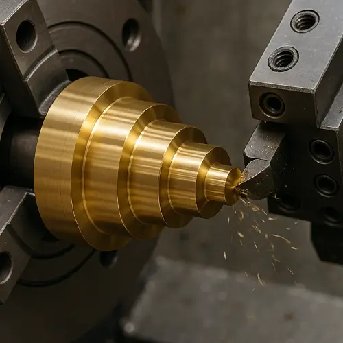
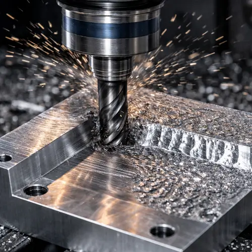
CNC machining is useful for custom heat sinks with special mounting holes, irregular base shapes, precision contact surfaces, integrated housing features, or low-volume production requirements. It is not always the lowest-cost process for every design, but it is often the most practical way to make and test a heat sink before committing to extrusion, die casting, or another dedicated production method.
What Is a Heat Sink?
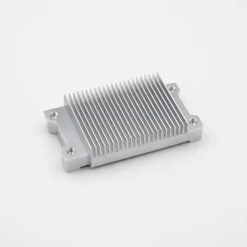
A heat sink is a metal component that moves heat away from a hot electronic part and releases that heat into the surrounding air. It is commonly used with processors, LEDs, power transistors, battery modules, power supplies, motor drives, communication equipment, and industrial control systems.
Most heat sinks include a flat base that contacts the heat source, a group of fins that increase surface area, and mounting features such as holes, threads, clips, or screw locations. Some are separate parts attached to a circuit board or power module. Others are built into the product housing, where the enclosure itself helps spread or release heat.
A custom CNC heat sink can include the base plate, fins, threaded holes, mounting features, connector clearance, and enclosure interfaces in one machined part. This is useful when a standard extruded heat sink does not match the required layout, component position, or assembly structure.
How Does a Heat Sink Remove Heat?
Heat usually moves from the electronic component into a thermal pad, thermal paste, or direct contact surface. It then enters the heat sink base, spreads through the metal, travels into the fins, and is carried away by the surrounding air.
The base plate spreads heat away from the small area where the component is mounted. The fins increase the amount of metal exposed to air. Airflow then determines how effectively that heat can leave the heat sink. A large fin area is not enough on its own if the fins are blocked by a nearby cover, packed too closely together, or installed where warm air cannot escape.
The aim is not simply to make the heat sink feel cooler. The real requirement is to keep the electronic component below its allowable operating temperature in actual working conditions. Ambient temperature, component power, contact area, enclosure space, mounting pressure, and airflow direction all affect the result. A heat sink that performs well in a 25°C room may behave very differently inside a product operating in a warmer industrial environment.
Heat Sink Materials: Aluminum, Copper, and Hybrid Designs
Material choice should be based on thermal load, available installation space, airflow, target operating temperature, weight limit, manufacturing route, and expected production quantity. Conductivity matters, but it is not the only factor that determines whether a heat sink will work well.
Aluminum Heat Sinks
Aluminum is the most common heat sink material for electronics. It is lightweight, reasonably priced, corrosion resistant, easy to machine, and suitable for anodizing. For many controllers, LED modules, power supplies, battery systems, industrial instruments, and communication devices, an aluminum heat sink provides enough thermal performance when the base size, fin structure, and airflow are designed correctly.
For CNC machining, 6061 aluminum is a practical choice when the heat sink needs custom mounting holes, threaded features, irregular base geometry, curved shapes, or integration with a product housing. It machines well and supports a wide range of finishes. A custom 6061 aluminum heat sink can also be combined with an aluminum CNC enclosure when the product needs both structural protection and thermal performance.
6063 aluminum is more common for extruded heat sinks. It is usually a better fit when the fin profile remains constant along the full length of the part and the expected quantity is high enough to justify extrusion tooling. A long straight heat sink with the same cross-section from one end to the other is often more economical as an extrusion than as a CNC-machined part.
Aluminum does have limits. It does not spread heat as quickly as copper, so a compact aluminum heat sink may struggle when a small component produces a high local heat load and the available fin area is limited. In that situation, the solution may involve increasing the base area, improving airflow, changing the mounting layout, using copper near the heat source, or adopting a hybrid design.
Copper Heat Sinks
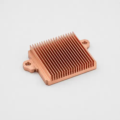
Copper transfers heat more readily than aluminum, which makes it useful when heat is concentrated in a small area and needs to spread quickly through the base. Copper heat sinks are often considered for high-power electronics, RF equipment, compact power modules, and products where the available mounting space is too limited for a larger aluminum solution.
Copper also brings clear trade-offs. It is heavier, more expensive, and usually costs more to machine than aluminum. Its softer surface can be marked more easily during machining, clamping, and handling. A full copper CNC heat sink may be justified when thermal performance is the main limitation, but it is not automatically the best option for every hot-running product.
Copper is not automatically the better heat sink material. For many electronic products, aluminum provides enough thermal performance at a lower weight and lower manufacturing cost. If the main issue is poor airflow or a closed enclosure, replacing aluminum with copper may not solve the problem by itself.
Aluminum and Copper Hybrid Heat Sinks
A hybrid heat sink uses copper where fast heat spreading matters most and aluminum where lower weight, larger surface area, and lower cost matter more. A common structure is an aluminum fin body with a copper base plate, copper insert, or copper heat spreader near the hot component.
This approach can work well when a small power device creates a concentrated hot spot but the product still needs a larger, lightweight aluminum fin area. The copper section spreads heat away from the source, while the aluminum body provides a broader surface for heat release.
Hybrid designs need careful attention to the contact surface and connection method. The interface between copper and aluminum must transfer heat well and remain stable during assembly. In humid or corrosive environments, the design should also consider surface protection and the risk of galvanic corrosion between dissimilar metals. A hybrid part can offer a better performance-to-cost balance than machining the entire heat sink from copper, but it adds manufacturing and assembly complexity.
Heat Sink Fin Design
Heat sink fins increase the surface area exposed to air, but more fins do not always mean better cooling. Fin thickness, fin spacing, fin height, base thickness, airflow, and manufacturing method must be considered together.
Heat Sink Fin Thickness and Spacing
Very thin fins may look efficient in CAD because they create more surface area in a small space. In real production, thin fins can bend during machining, transport, assembly, or handling. They also require smaller cutting tools and more careful machining, which increases cost.
Fin spacing matters just as much. If fins are packed too closely, air may not move effectively through the channels. For natural convection, narrow gaps can trap warm air and reduce the benefit of extra fin area. For forced-air cooling, the spacing still needs to allow the fan to push air through the fin channels rather than around the outside of the heat sink.
CNC machining also needs enough room for the cutter and chip removal. A design with very thin, closely spaced, deep fins may be possible, but it can take much longer to machine and may require more careful support. In many cases, a slightly wider fin gap or a slightly larger heat sink gives a better balance between thermal performance and manufacturing cost.
Heat Sink Fin Height and Base Thickness
Taller fins provide more surface area, but the benefit is limited by airflow and machining stability. Very tall fins may require longer tools, which are more likely to vibrate and leave inconsistent surface finish. If air does not move through the full fin height, making the fins taller may add cost without providing meaningful thermal improvement.
The base thickness affects how heat spreads from the source into the fin area. A base that is too thin may allow heat to remain concentrated near the component instead of distributing it across the heat sink. A base that is much thicker than necessary adds weight, material cost, and machining time.
The best base thickness depends on the size of the heat source, the contact area, the mounting method, the heat load, and the overall space available. A large power module may need a different base design from a small LED board, even when both use an aluminum heat sink.
Heat Sink Design for Airflow and Enclosures
A heat sink should be designed as part of the complete product, not as an isolated metal component. Natural convection and fan cooling behave differently, and both depend on the space around the fins.
For natural convection, warm air needs a clear path to rise through or around the fin channels. The direction of the fins, the orientation of the product, and the distance between the heat sink and nearby walls can all affect performance. A vertical fin arrangement may work better than a horizontal one in some naturally cooled products because it supports upward airflow.
For forced-air cooling, the key question is whether the fan creates a usable airflow path through the heat sink. The design needs an inlet, a path across the fins, and an outlet for warm air. A fan positioned near a heat sink does not guarantee effective cooling if the air immediately recirculates inside the product.
When a heat sink is installed inside an electronic housing, the enclosure design becomes part of the thermal system. Vent locations, cover clearance, component position, fan direction, and the size of the internal air path all matter. A compact CNC enclosure with no useful airflow path can limit the performance of even a well-designed heat sink.
Thermal performance should be confirmed through appropriate simulation, prototype testing, or both. A manufacturing review can identify issues with material choice and machining access, but it does not replace validation of the final product under real operating conditions.
CNC Heat Sink Design and Machining
CNC machining is especially useful when a heat sink needs features that are difficult to achieve with a standard extrusion. These may include non-standard mounting patterns, curved or irregular base shapes, threaded holes, different fin areas on one part, integrated enclosure walls, connector clearance, or precision contact surfaces.
A CNC-machined heat sink must be designed for cutting tools as well as thermal performance. Extremely narrow fin channels, deep slots, sharp internal corners, and unsupported thin walls can increase machining time and reduce stability. Internal corners need practical radii because milling cutters are round. Mounting holes and threaded features need enough surrounding material to remain strong during machining and assembly.
The heat source contact surface also needs attention. If a thermal pad or paste will be used, the mounting face should be flat enough to support consistent contact pressure. If the heat sink also acts as a structural bracket or enclosure wall, the machining order should protect critical surfaces from clamp marks and distortion.
Very thin fins, deep channels, and complex base geometry may require special support during machining. Proper CNC workholding and fixtures help control vibration, prevent part movement, and keep critical holes or mounting faces aligned across repeat orders.
Heat Sink Manufacturing: CNC vs Extrusion vs Die Casting
The best manufacturing method depends on part geometry, quantity, design stability, and target cost. CNC machining is not always the final production route, but it is often the best way to validate a design before investing in a dedicated process.
| Manufacturing Method | Best For | Main Advantage | Main Limitation |
|---|---|---|---|
| CNC Machining | Prototypes, low-volume production, special mounting features | Flexible design, accurate holes, irregular geometry, and integrated enclosure features | Higher unit cost for long straight fin structures |
| Aluminum Extrusion | Long heat sinks with a fixed cross-section | Lower cost for stable repeat production | Limited to one consistent profile along the length |
| Die Casting | High-volume complex heat sink structures | Lower unit cost after tooling | Tooling cost and slower design changes |
| Skived Fin | Dense thin-fin heat sinks | High fin density in a compact area | More process limits and higher manufacturing complexity |
CNC machining is usually the right choice for prototypes, low-volume projects, custom mounting features, irregular geometry, and heat sinks integrated with housings. It allows the design to be changed without modifying an extrusion die or casting mold.
Aluminum extrusion is often more economical when the fin profile remains constant and the heat sink is long or repeated across a stable product line. Die casting becomes more practical when the shape is complex, the design has already been validated, and the production quantity is high enough to spread tooling cost across many parts.
Heat Sink Design for Production
A heat sink that works as a CNC prototype should also be reviewed for the next production stage. The goal is not only to make the first part successfully, but to avoid creating a design that becomes unnecessarily expensive when quantities increase.
For prototype and low-volume orders, CNC machining gives the most flexibility. It supports design revisions, different mounting patterns, multiple enclosure versions, and real-material testing without production tooling. This is often the right approach while the thermal layout, PCB position, fan arrangement, and enclosure structure are still changing.
As a project moves toward repeat production, the design should be reviewed for its long-term manufacturing route. A heat sink with a constant cross-section may be a good candidate for extrusion. A high-volume part with more complex external shape may justify die casting. A very compact design with thin fins may need a different process altogether.
The earlier these choices are considered, the easier it is to avoid expensive changes later. A heat sink that looks compact in CAD but uses extremely thin fins, very deep narrow channels, or difficult internal features may be practical for a few CNC prototypes but poor for higher-volume production.
Heat Sink Cost and Quantity
Heat sink cost is affected by material, size, fin geometry, mounting features, machining time, finishing requirements, and quantity. Aluminum is usually easier to control from a budget perspective, while copper and hybrid structures are generally more expensive because of material cost and additional manufacturing steps.
Fin design has a major effect on price. Thin, high, closely spaced fins require smaller and longer tools, more careful cutting, and sometimes more complex support. Deep channels and multi-sided features also increase setup time. A heat sink with several mounting holes, threaded features, a precision base surface, and integrated enclosure geometry may cost more than a simple extruded profile, but it can remove the need for extra brackets or secondary parts.
A small and simple aluminum CNC heat sink prototype may cost around US$50–150, especially when it has a basic base plate, several fins, and simple mounting holes. A custom aluminum heat sink with more fins, threaded holes, a machined contact surface, and surface treatment may often fall around US$150–500. A more complex heat sink with dense fins, special mounting features, integrated enclosure geometry, multi-sided machining, copper material, or a copper-aluminum hybrid structure may reach US$500–1,200+ at prototype quantity.
These ranges are early budgeting references rather than fixed prices. The final CNC machining cost depends on material, thermal requirements, overall size, fin structure, mounting method, surface finish, quantity, inspection needs, and whether special fixture support is required.
Get a Custom Heat Sink Quote
A custom heat sink should be reviewed for both thermal performance and manufacturability. A CAD model and 2D drawing should show the base shape, fin geometry, mounting holes, threaded features, and enclosure interfaces. It also helps to provide the heat source location, approximate power dissipation, expected ambient temperature, available installation space, cooling method, material preference, and expected quantity.
JeekRapid provides CNC machining services for custom aluminum, copper, and hybrid heat sinks for prototypes and low-volume production. The engineering team can review whether CNC machining, aluminum extrusion, die casting, or another process is the most practical fit for the part structure and production plan.