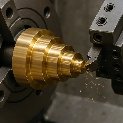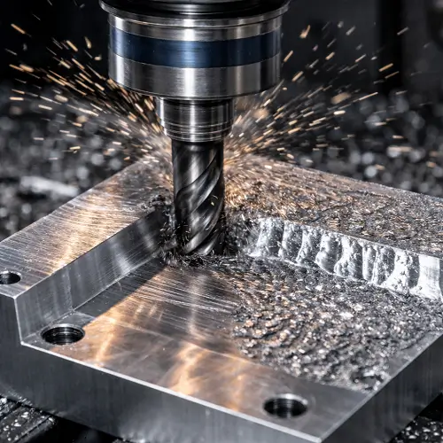
Circular milling uses a rotating cutter traveling around a circular path to machine round holes, pockets, and outside profiles. It is useful when a part needs several opening sizes, a custom-diameter recess, or circular features alongside other milled details. One suitable cutter can produce different diameters by changing its path.
For a customer, the main benefit is flexibility. A plate with several different openings does not necessarily need a separate drill for every diameter. A rectangular housing with a round mounting recess can often have that recess machined while it is already set up for milling.
Whether circular milling is the right choice depends on what the feature needs to do. An opening for a cable connector, a recessed seat for a cover, and a bearing bore may look similar, but their fit and finishing requirements are different.
What Is Circular Milling?
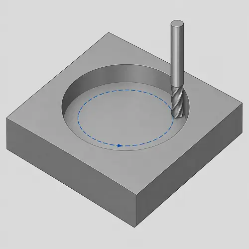
In CNC circular milling, the cutting tool spins while moving around the center of the feature. The workpiece usually stays clamped in place, and the machine coordinates its axes to create the circular movement. This movement is called circular interpolation.
For example, a plate may need a 1.000-inch hole. Instead of using a drill that matches the finished diameter, the shop can use a smaller end mill to remove material and machine the wall to size. The tool cuts around the opening rather than producing the entire diameter in a single drilling pass.
If the cutter circles at a fixed depth, it makes a circular pass. If it also moves downward while circling, it follows a helical path. This is known as helical interpolation and allows a suitable cutter to deepen an opening progressively.
The customer does not need to specify the CNC code. The important information is the finished hole size, depth, location, and intended fit. The shop chooses the toolpath and entry method around those requirements.
When Is Circular Milling a Good Choice?
Circular milling is particularly useful for different hole diameters, circular recesses, and small batches where diameter-specific tooling may not be worthwhile. It can also make sense when the part already requires milling, allowing round and rectangular features to be produced in the same setup.
Consider an equipment plate with openings for several connectors. Each connector may need a different clearance diameter. A suitable end mill can machine those openings by changing its path, so the shop may not need to purchase a separate drill for every size.
That flexibility is useful during prototype development. If an opening needs to become slightly larger in the next revision, the shop may be able to adjust the program and keep the same cutter. Tool reach, material, and the remaining wall thickness still need to suit the change.
Circular milling is also useful for a housing that combines pockets, mounting holes, and a round locating recess. Keeping suitable features in one setup can reduce handling and help maintain their positions relative to each other.
However, milling every hole is not automatically economical. If a plate needs hundreds of identical holes and suitable drilling tools are available, drilling may be faster. The practical choice depends on the whole order, including quantity, preparation, and finishing—not just whether the machine can cut a circle.
What Parts and Features Can Circular Milling Produce?
Circular milling is used for access openings, recessed seats, counterbores, and raised circular features. Looking at what fits into or around the feature makes it easier to understand why the process is useful.
Circular Holes and Access Openings
Circular hole milling can produce openings for connectors, sleeves, instrument components, and other parts passing through a plate or housing.
For a clearance opening, the goal may simply be to leave enough room for installation. There is little value in requesting a bearing-seat tolerance if the hole only needs to clear a cable connector. A suitable clearance and a properly deburred edge may be the important requirements.
An existing hole can also be enlarged. Correcting its position is more limited: enough material must remain around the intended final boundary. If the original hole already extends outside that boundary, further machining cannot replace the missing material.
Circular Pockets and Counterbores
Circular pocket milling creates a round recess with a floor at a specified depth. It can provide a seat for a round cover, insert, sensor, or other component.
Here, “does it fit?” includes more than diameter. A round insert might pass through the opening but fail to sit flat because its lower edge contacts the radius where the pocket wall meets the floor. The drawing should make the seating requirement clear so the mating edges can be checked.
A counterbore creates a larger recessed area above a smaller hole, often to accommodate a fastener head. Both its diameter and depth matter: the head needs room around it and must sit at the intended height.
Circular Bosses and Outside Profiles
External circular milling removes material around a raised round feature. A rectangular mounting plate, for example, may have a circular boss that locates inside a mating housing.
This allows a round locating feature to be machined alongside the plate’s holes and pockets. The entire component does not need to be cylindrical.
For a part that is mainly a round shaft or sleeve, turning may be more practical. Circular milling is especially useful when the round feature is one part of a more complex milled component.
Circular Milling vs Drilling and Boring: Which Should You Choose?
Choose the process around the finished requirement. Drilling is often efficient for repeated holes with suitable tools available. Circular milling offers flexibility for different diameters and recessed shapes. Boring can finish an existing hole when its size and geometry need closer control.
A small batch of housings with several custom openings may suit circular milling. A production plate with many identical through-holes may suit drilling. A precision bearing bore may be milled first and then finished by boring.
| Part requirement | Process worth considering | Reason |
|---|---|---|
| Many identical standard-size holes | Drilling | A suitable drill can produce repeated holes efficiently |
| Different opening diameters in a small batch | Circular milling | One suitable cutter may handle several sizes |
| Round recess with a seating floor | Circular pocket milling | The wall and floor can be machined as part of the recess |
| Critical bearing or locating bore | Milling followed by boring, or another suitable finishing method | The final process can be selected around the fit and geometry |
| Mostly cylindrical shaft or sleeve | Turning | The overall part shape often suits lathe machining |
These methods can work together. Milling a hole close to size and boring it afterward is a practical process choice, not a sign that the first operation failed.
Unless a particular manufacturing method is required, specify the result and let the supplier propose how to achieve it. That gives the shop room to balance quality, tooling, and CNC machining cost.
Can Circular Milling Produce a Bearing Fit?
Circular milling can produce some bearing seats, but there is no single tolerance that applies to every circular milled hole. The achievable result depends on bore diameter, depth, material, wall thickness, equipment, and inspection requirements.
A shallow bore in a rigid housing is a different job from a deep bore surrounded by a thin wall. The first may be suitable for finish milling. The second may need a different machining sequence or a dedicated finishing operation.
The useful question for the customer is: “Will this bore meet the specified fit after machining and surface treatment?” The supplier should explain how the result will be produced and checked.
Diameter alone may not describe the entire fit. A bore can be the right size near its entrance but become smaller farther down. This variation is called taper. If the bearing or sleeve engages deeper into the hole, measuring only the entrance may miss the problem.
Roundness also matters where the application requires it. A diameter measurement in one direction does not fully describe the shape of the hole. A precision bore may need checks at different positions and depths, together with any geometric controls shown on the drawing.
For a bearing seat, provide the bearing information and the approved fit requirements. The supplier should not have to guess whether the assembly needs clearance or interference from the nominal diameter alone.
What Can Make Circular Milling Difficult?
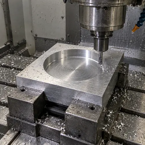
Circular milling becomes more demanding when the feature is deep, access is restricted, the surrounding wall is thin, or the finish requirement is difficult to achieve. These conditions can change the tooling, machining time, and finishing approach.
A deep pocket requires more tool reach. A long, slender cutter can bend slightly under cutting force, affecting the wall size or leaving taper. If a sleeve must fit through the full depth, identify that requirement early. The shop may recommend a different tool or a separate finishing operation.
A thin housing creates another problem. Clamping can distort the part, and the circular feature may change shape when released. Simply tightening the fixture harder can make matters worse. The workholding and cutting sequence need to suit the remaining wall thickness.
Chip removal is important inside a pocket, too. Chips trapped around the cutter can damage the surface or disrupt cutting. A deep, enclosed recess may therefore need a more controlled approach than a shallow opening, even when their diameters are the same.
Finally, visible tool marks do not always mean the part is unsuitable. For a clearance opening, they may be acceptable. For a sealing or sliding surface, the finish may need tighter control. State which surfaces matter rather than requesting the same finish everywhere.
Burrs in CNC machining should also be addressed at entrances, exits, and intersecting holes. The edge should allow the intended assembly without removing material that is needed for fit or support.
What Should a Drawing Show for Circular Milled Features?
For a circular hole, show its diameter, tolerance, location, and whether it passes through the part or stops at a specified depth. For a circular pocket, include the depth and any requirements for the seating floor and wall-to-floor corner.
The reason for those details should be straightforward. If a round insert must sit against the bottom of a recess, say so. Otherwise, the opening may be large enough while the corner radius prevents the insert from seating fully.
If the hole locates another component, show where its center belongs relative to the relevant mounting features. A correctly sized bore in the wrong position can still prevent assembly.
Also state whether the dimensions apply after anodizing, plating, or another treatment. A fit checked before treatment may not represent the finished part. The supplier needs this information when planning allowances, masking, and final inspection.
If the design is still being developed, explain what the feature receives and how it should assemble. A cover that drops into a recess has different needs from a sleeve that must remain fixed by interference. That context helps guide the review, while final acceptance limits should be agreed before production.
Circular Milling for Custom CNC Parts
Circular milling is a practical option when custom parts need different opening sizes, round recesses, or circular locating features alongside other milled details. For demanding fits, it can be combined with boring or another finishing process to meet the drawing requirements.
JeekRapid provides CNC machining services for custom metal and plastic parts. Send the CAD model and available drawing with the material, quantity, and finishing requirements for review. Identify any circular feature that must fit a bearing, sleeve, cover, or connector so the team can assess a suitable machining and inspection approach.