If a part “looks fine” but still won’t assemble, burrs are usually the reason. Dimensions can be on print and surface finish acceptable, but edge condition causes assembly failure. A small exit burr can stop a press-fit, a micro burr on a sealing land can cause a slow leak, and a sliver of copper burr can end up exactly where nobody wants it — inside a connector or a housing.
If you have ever had to stop an assembly line because someone is hand-scraping edges at the last minute, you already know burrs are not a cosmetic issue. Burrs are a process stability issue. In daily production work at JeekRapid, burr behavior is reviewed alongside tolerance and surface finish during process planning.
The good news is that burrs are predictable once the cutting mechanics, exit conditions, and finishing plan are treated as part of the manufacturing process — not a cleanup task.
Why Burrs Occur in CNC Machining
Burrs form because cutting is not a perfect shear. Material ahead of the cutting edge is compressed and plastically deformed before it separates. When the tool approaches a free edge — like the exit of a drilled hole or the end of a contour — the material loses support and bends outward instead of breaking cleanly.
Heat and low chip thickness make the problem worse. When chip thickness drops below about 0.0008–0.002 in for aluminum and 0.0004–0.0012 in for stainless steel, cutting starts to turn into rubbing. Rubbing creates heat, softens the surface, and increases burr size. That is why “slowing down for a nicer finish” often produces larger burrs instead.
Primary Causes of Burr Formation
Most burr problems come from a few practical issues: worn cutting edges, unstable cutting parameters, flexible part features, and material behavior. Dull tools push metal instead of slicing it. Very light finishing passes smear material instead of forming a clean chip. Thin walls and long overhangs deflect, so burr height changes along the same edge.
If burrs vary from part to part, it is almost always a process consistency problem — tool life control, fixturing repeatability, or an exit path that changes slightly each cycle.
Common Types of CNC Burrs
Exit burrs appear at tool departure points: drilled hole exits, contour endpoints, slot ends, and breakout features.
Rolled burrs look like thin lips folded over — common in aluminum and copper.
Side burrs form along walls from compressive stress.
Tear burrs look irregular and ragged, often caused by vibration.
Micro burrs can be hard to see but still cause assembly failure — especially in tight fits, sealing surfaces, and electrical contacts.
How Burrs Affect Part Performance
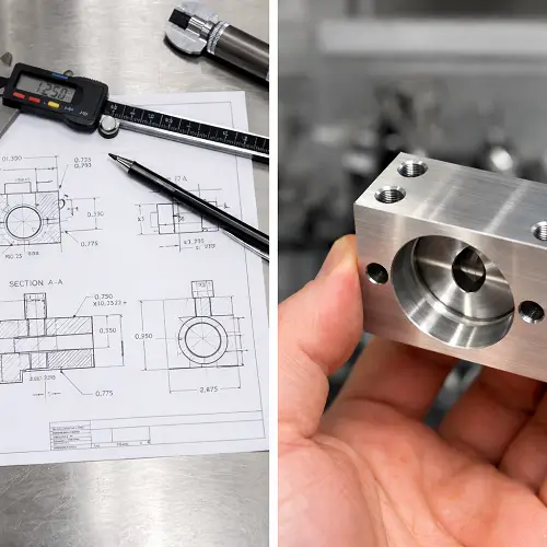
Burrs distort inspection results because probes and calipers touch the burr instead of the true edge. Burrs jam press-fits, chip anodized surfaces, and cut O-rings during installation. Burrs also shorten fatigue life by acting as tiny stress concentrators.
In electrical and medical products, burr debris causes contamination and short circuits. If your parts must assemble cleanly, burr control is not optional.
How to Control Burrs in CNC Machining
The most effective approach is to control burrs during cutting, not after. Sharp tools, stable chip thickness, and proper support of thin features significantly reduce burr formation before any secondary process is required.
Tool exit matters more than most people realize. Changing cut direction, modifying lead-in or lead-out, or exiting into a non-functional surface often reduces burrs by 40–70% without adding cycle time.
Supporting thin ribs, walls, and narrow tabs also helps. Even simple fixture changes can cut burr height dramatically by reducing deflection and chatter.
Finally, small controlled chamfers (for example 0.008–0.016 in on most aluminum parts) turn unpredictable burrs into stable, measurable features that are much easier to manage.
Deburring Methods and Finishing Options
If you are choosing a deburring method, start with one question:
Is the burr on an outside edge you can reach, or trapped inside a hole intersection?
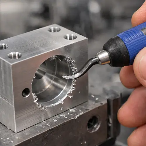
CNC Edge Breaking
Programmed chamfers or radii provide the most consistent results. For production parts, this is usually the most reliable solution.
Brush Deburring
Good for light burrs on aluminum and stainless steel when dimensions must stay tight. Brush condition must be monitored to keep results consistent.
Vibratory Finishing
Effective for small batch parts with non-critical edges. Not recommended for parts with strict edge-geometry requirements.
Thermal & Electrochemical Deburring
Used for internal burrs and intersecting holes that mechanical tools cannot reach, especially in fluid or precision components.
Why choose JeekRapid for burr removal?
If burrs are slowing down assembly or forcing repeated handwork, that is a sign the process upstream is unstable. The right fix depends on what you are seeing — sharp outside edges, hole-exit burrs, or internal cross-hole burrs.
In many projects, a short process review saves far more time and cost than another round of trial-and-error on the shop floor.
For parts that need additional support, JeekRapid can review drawings, identify the main burr sources, and recommend a stable machining and finishing approach. If you already have drawings or sample parts, you can submit them to request a quotation, and the engineering team will normally respond within 24 hours.
FAQ
Can burrs be completely eliminated?
Not completely. The goal is to reduce burrs to a level that does not affect function or assembly.
Do tighter tolerances increase burr risk?
Yes. Smaller tools and lighter cuts increase burr sensitivity.
When should deburring be planned?
During DFM, before production begins.