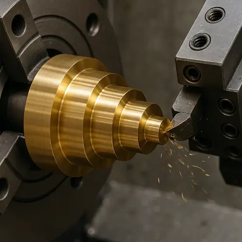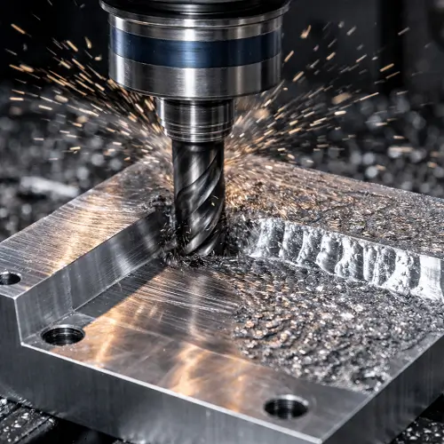
A valve body connects the piping, contains the flow passages, and supports the components that open, close, or regulate flow. Its machined features affect whether the valve assembles correctly, moves freely, and meets its sealing requirements.
For a custom order, reproducing the outside shape is only part of the job. The manufacturer must also reach the internal features, maintain their relationship to each other, remove hidden burrs, and verify the finished dimensions. Understanding these requirements helps customers prepare clearer drawings and compare valve body machining quotations on the same basis.
What Is Valve Body Machining?
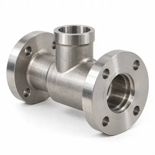
Valve body machining creates the finished bores, seat pockets, connection ports, and mating faces needed by a valve assembly. Depending on the design and production quantity, machining may start with solid bar or block, or finish selected features on a casting or forging.
The valve body is the main housing, not the complete valve. A ball, plug, spool, needle, or disc controls flow inside it. Seats, seals, guides, and other components work with the body to establish movement and sealing.
Some bodies contain an integral seating surface. Others hold a separate seat ring or cartridge. This difference changes what needs to be machined and inspected. A pocket that supports a replaceable seat has a different function from a surface that directly contacts the closing element.
A valve body can resemble a CNC machined manifold, especially when both contain several ports and internal passages. A manifold primarily connects and distributes flow between components, while a valve body houses the mechanism that controls flow. Some designs combine both functions.
What Types of Valve Bodies Can Be CNC Machined?
Ball Valve Bodies
Ball valve bodies contain a rotating ball and its seating arrangement. Machining may include the main cavity, seat pockets, stem opening, end connections, and the interfaces between separate body sections.
The seat pockets must position and support the seats correctly. Their diameters, depths, and relationship to the mating components affect how the internal assembly fits. In a split-body valve, the body sections must also align when fastened together.
For quotation, include the relevant seat, stem, and end-piece information. A manufacturer can machine individual dimensions from a body drawing, but assembly information helps identify which relationships are critical.
Needle Valve Bodies
Needle valve bodies often combine a stem interface, a small flow passage, a seating feature, and connection ports. The seating area may sit deep inside a narrow opening, making tool access and inspection more difficult.
The drawing should define the seat profile and its relationship to the stem or guide features. If the seat requires a finishing operation beyond ordinary machining, that requirement should be stated.
Small passages also need effective deburring. A loose chip or damaged seating edge can affect operation even when the external dimensions meet the drawing.
Hydraulic and Pneumatic Valve Bodies
Hydraulic and pneumatic valve bodies may contain spool bores, cartridge cavities, cross-drilled passages, threaded ports, and seal grooves.
For a spool-type valve, checking the bore diameter at one location is not enough. Variation along the bore, out-of-roundness, surface condition, and misalignment can affect movement and internal leakage.
If the body accepts a purchased cartridge valve, identify the exact cavity specification and revision. Similar-looking cavities should not be treated as interchangeable without checking their dimensions and sealing details.
Cooling and Instrumentation Valve Bodies
Cooling equipment, laboratory instruments, and analytical systems often use compact valve bodies with customized port positions and mounting features.
Installation space is an important part of the design. A body may fit inside the equipment while leaving too little room to tighten a fitting, connect a hose, or remove an actuator.
Include the surrounding layout when access is restricted. Also specify any special cleaning requirements. A body intended for an ordinary coolant circuit should not automatically receive the same treatment as a component used with high-purity gas or sensitive analytical fluids.
Should a Valve Body Be Machined from Solid, Cast, or Forged Material?
Machining from solid stock is often worth evaluating for prototypes, smaller batches, and designs that may change. Port positions, mounting features, and external geometry can be revised without first changing a casting or forging tool.
However, the internal shape must remain accessible. A curved passage enclosed inside a solid CAD model cannot necessarily be produced with ordinary drilling and milling. The design may require intersecting drilled holes with plugs, a split construction, or a different manufacturing route.
A casting can provide a near-net shape and internal passages that would be difficult to machine from solid material. CNC machining then produces the functional bores, connection features, sealing faces, and mounting surfaces.
Cast valve body machining requires adequate machining allowance and suitable locating references. If a casting leaves insufficient material around a seat pocket or places an internal passage incorrectly, machining cannot simply restore the missing material.
A forging may be specified where the valve design requires a particular material condition and a suitable forged shape is available. Its use does not remove the need to control finished dimensions, material documentation, and inspection.
If you supply castings or forgings, provide both the blank drawing and the finished-part drawing. Agree on incoming inspection and how defects discovered during machining will be handled. This avoids uncertainty over whether a rejected part resulted from the supplied blank or the machining operation.
Which Materials Are Used for CNC Machined Valve Bodies?
Material selection should follow the fluid, operating temperature, pressure design, corrosion conditions, and applicable product requirements. A material that is easy to machine is not necessarily appropriate for the intended service.
Stainless Steel
Stainless steel valve bodies are used where the selected grade provides suitable corrosion resistance and mechanical properties. The exact grade must match the medium and operating environment.
“Stainless steel” alone is not a complete purchase specification. A wrought grade and a cast grade with similar chemistry are not automatically interchangeable. Identify the required material specification, condition, and supporting documentation.
Stainless steel valve body machining requires attention to work hardening, tool wear, and burr formation. Internal bores and seat pockets need to meet their specified condition, regardless of how smooth the outside of the body appears.
Brass
Brass is commonly considered for suitable instrumentation and valve components because it machines efficiently and can produce clean threads and detailed features.
The alloy still needs to suit the application. Water chemistry, corrosion exposure, and restrictions on lead content may affect the choice. A readily available machining brass should not replace a specified alloy without approval.
For threaded brass bodies, define both the port thread and the sealing arrangement. A fitting that screws into the port does not prove that the connection is correctly specified.
Aluminum
Aluminum valve bodies can be useful where low weight matters and the alloy is compatible with the service conditions. Applications may include pneumatic equipment, cooling systems, and other appropriately designed assemblies.
Threads, close-fitting bores, and seal grooves need to be considered together with any surface treatment. A coating can change a bore or groove dimension, so the drawing should identify the required finished condition.
Aluminum should not be chosen solely to reduce machining time. The complete design must still satisfy the application’s structural and environmental requirements.
Carbon and Alloy Steel
Carbon and alloy steels may be specified where their mechanical properties and service characteristics suit the valve. Corrosion protection or another surface treatment may be necessary.
The material condition and any heat treatment should be established before quotation. If treatment occurs after rough machining, the process may need additional allowance and final finishing to achieve the drawing requirements.
How Are Valve Bodies CNC Machined?
Establishing Machining References
The manufacturer first determines how to locate and hold the workpiece. These reference surfaces and features help maintain the relationship between bores, seat pockets, ports, and mating faces across different operations.
A block-shaped body may be located against machined faces. An irregular casting may need dedicated supports because its as-cast surfaces are less consistent.
Clamping must also avoid distorting the part. A bore that measures correctly while the body is heavily restrained may change after the clamps are released. Thin sections and uneven support make this especially important.
Rough Turning and Milling
Rough machining removes most of the unwanted material and establishes the general shape. It may create the main cavity, prepare mounting faces, and leave controlled stock on critical features for later finishing.
Separating roughing from finishing gives the manufacturer a way to manage heavy material removal before completing sensitive surfaces. Where needed, the process can include an intermediate check or an agreed treatment before final dimensions are produced.
The body may look nearly finished after rough machining, but its functional bores and sealing interfaces may still require further work.
Drilling, Boring, and Reaming
Drilling creates openings and flow passages. Boring enlarges or finishes an existing opening and can help control its position and geometry. Reaming can finish a suitable prepared hole to its required size and surface condition, but it is not a cure for every positioning or alignment error.
Valve bore machining must follow the function of the bore. A passage that only carries fluid does not necessarily need the same controls as a bore guiding a spool.
Deep internal features may require longer tools, which are more susceptible to deflection and vibration. Tool access, chip removal, and the inspection method should be considered before the machining route is finalized.
Seat and Seat-Pocket Finishing
Valve seat machining depends on whether the body contains the actual sealing surface or only the pocket supporting a separate seat.
For an integral seat, the profile, location, and surface condition form part of the sealing interface. For a replaceable seat ring, the body pocket must position and support that ring according to the assembly design.
Some designs require grinding, lapping, or another finishing operation. These requirements should be defined on the drawing rather than assumed to be included in standard machining.
Port Threads and Seal Grooves
Ports may be tapped or thread milled, depending on their size, access, material, and specification. The drawing should identify the thread standard, required depth, and any associated sealing face or counterbore.
Tapered pipe threads and straight-thread connections do not all seal in the same way. A correct nominal thread size is only part of the interface.
O-ring groove design must match the selected seal and mating geometry. Groove dimensions, surface condition, and entry edges affect whether the seal can be installed without damage and compressed as intended.
Flange Faces and Bolt Patterns
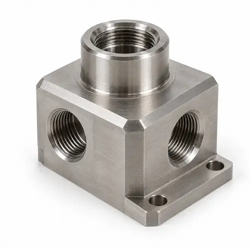
Flange machining establishes the connection face, relevant sealing geometry, and bolt pattern. The holes must align with the mating flange, while the face must meet the requirements of the specified gasket or seal.
A visibly polished face is not automatically the correct finish. The drawing or applicable connection specification should establish the required surface condition.
Bolt access also matters. Check whether the assembled layout leaves room for fasteners and installation tools. Accurate holes are of little help if the surrounding geometry prevents the joint from being assembled properly.
JeekRapid provides drawing-based CNC machining for custom valve bodies and related components, with internal access, critical interfaces, finishing, and inspection requirements reviewed before production.
Which Valve Body Features Need Precise Machining?
The critical features depend on how the valve operates. Applying a tight general tolerance to every dimension does not replace identifying the surfaces that control fit, movement, and sealing.
| Feature | What it controls | What the drawing should establish |
|---|---|---|
| Spool or guide bore | Movement and operating clearance | Size, geometry, surface finish, and reference features |
| Integral seat or seat pocket | Sealing contact or seat location | Profile, depth, position, finish, and mating details |
| Stem or guide opening | Alignment with related components | Bore requirements and relationship to the seat or guide |
| Connection port | Fitting installation and sealing interface | Thread standard, depth, and associated sealing geometry |
| Body joint or bonnet face | Assembly location and joint sealing | Relevant flatness, finish, groove details, and fastening pattern |
| Mounting features | Installation in the equipment | Hole locations, reference surfaces, and required clearances |
Consider a body containing a stem opening above a seat. Both features may meet their individual diameter limits but still be incorrectly aligned. The drawing needs to control their relationship, not only their sizes.
Likewise, a seat pocket can have the correct diameter but the wrong depth for the selected seat and closing element. Supplying the relevant assembly details helps the manufacturer understand which dimensions must be evaluated together.
Why Can a Machined Valve Body Leak or Cause Sticking?
External Leakage
External leakage allows the medium to escape outside the valve. It may occur at end connections, body joints, stem sealing areas, or through a defective pressure-containing wall.
Machining-related causes can include an incorrect port form, damaged sealing face, or unsuitable groove geometry. Defects in the starting material may also become visible during machining or testing.
The leak location should be identified before deciding on a correction. Changing a surface finish will not resolve an incorrect fitting, damaged seal, or defect elsewhere in the body.
Internal Leakage
Internal leakage occurs when fluid passes through a path that should be closed or restricted. Possible causes include damage at the seating contact, incorrect seat location, contamination, or an unsuitable fit between internal components.
The acceptance requirement depends on the valve design and service. Some arrangements permit a specified leakage level, so “no leakage” is not a complete test instruction.
A bare body can meet its dimensional requirements without proving the shutoff performance of the complete valve. That performance must be evaluated under the agreed assembly and test conditions.
Sticking or Restricted Movement
A spool or stem may bind because of taper, out-of-roundness, misalignment, contamination, or distortion after fastening. Measuring only the bore entrance may miss the affected area.
For example, a component may move freely before the bonnet or mounting bolts are tightened but bind afterward. That points toward an assembly relationship or distortion that needs investigation, rather than automatically indicating that the bore should be enlarged.
Increasing clearance without identifying the cause may reduce sticking while creating excessive internal leakage. The corrective action should follow measurements of the actual assembly.
How Are Machined Valve Bodies Inspected and Cleaned?
Inspection should follow the functional requirements on the drawing. Overall length, width, and a few hole diameters are not enough when the part contains critical internal relationships.
Depending on the specification, checks may include bore measurements at several depths and orientations, thread gauging, surface roughness measurement, and coordinate measurement of related features. Geometric requirements need suitable inspection methods; a size measurement alone does not establish roundness or alignment.
Internal burrs require a separate plan. Intersecting drilled passages can leave edges that are difficult to reach and inspect. If these break away later, the particles may damage a seal, obstruct movement, or enter connected equipment.
Cleaning requirements should therefore be defined where they affect acceptance. “Clean after machining” does not specify an allowable particle level, prohibited residue, drying condition, or packaging method.
Testing must also be separated by purpose. A body pressure-boundary test checks a different requirement from an assembled valve seat-leakage test. Agree on the applicable procedure, test medium, conditions, acceptance criteria, documentation, and responsible party before quotation.
After acceptance, ports and functional surfaces should be protected from damage and contamination during handling and shipment.
What Should You Send for a Valve Body Machining Quote?
Send the 3D model and 2D drawing together where available. Identify the material specification, quantity, drawing revision, surface treatment, and critical requirements.
Include the relevant seat, cartridge, stem, spool, bonnet, or fitting information when it determines a body interface. The manufacturer needs to know what the machined features must match.
State whether the order covers a bare machined body, a body with installed components, or a complete assembled and tested valve. Valve body machining services do not automatically include purchasing internals, assembly, or functional testing.
For supplied castings or forgings, include the blank drawing, material records, and incoming acceptance requirements. Clarify how machining allowance and any defects discovered during processing will be reviewed.
Finally, identify required inspection reports, cleanliness criteria, and testing. If an item remains undecided, mark it as an open question rather than leaving it unstated. This helps a custom valve body manufacturer distinguish a firm manufacturing requirement from an assumption.
Conclusion
Valve body machining produces the bores, seat interfaces, ports, and connection faces that allow a valve to assemble and function as designed. The useful questions are which features matter, how they relate to the mating components, and how the finished body will be inspected and accepted.
JeekRapid supports custom valve body machining from customer drawings. Send your CAD files, drawings, material specification, and quantity for a manufacturability review and quotation. If you already have castings or forgings, include their specifications; if a seat, bore, or connection detail remains uncertain, highlight it so we can review the machining requirements before production.