Hydraulic fittings connect fluid lines to pumps, valves, cylinders, and other equipment. Their connection geometry, sealing surfaces, and internal passages affect how the assembly fits together and whether it operates without leakage.
For custom equipment, finding the right fitting involves more than choosing a thread size. The part may also need a particular length, outlet direction, mounting feature, or combination of connections. Understanding these requirements helps buyers and engineers choose suitable fittings and prepare custom designs for manufacturing.
What Are Hydraulic Fittings?
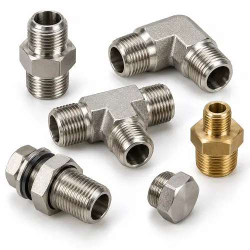
Hydraulic fittings are connection components that join hoses, tubes, pipes, and equipment ports in a hydraulic system. They provide a contained path for fluid while allowing components to be assembled, disconnected, or arranged in different directions.
A fitting can connect a line directly to a valve, turn the flow path around an obstruction, divide a connection into branches, or adapt one interface to another. Plugs and caps close connections that are not in use.
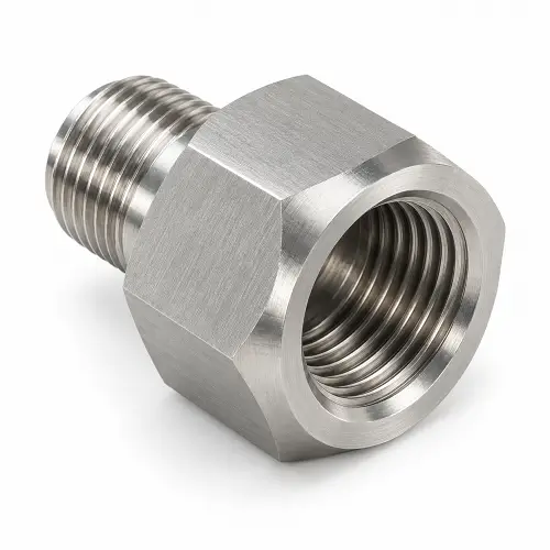
The term hydraulic adapter generally describes a component that joins two interfaces. Those interfaces may differ in size, connection standard, or male and female configuration. A hydraulic hose fitting includes an end specifically designed to attach to a compatible hose.
This distinction matters when ordering custom parts. A machined adapter body and a complete hose assembly require different manufacturing and verification steps. The drawing should identify which component is being supplied and how it connects to the rest of the equipment.
What Are the Different Types of Hydraulic Fittings?
Hydraulic fitting types can be grouped by their body shape and their connection design. The body determines where the fluid line goes. The connection design determines how the parts attach and seal.
Straight Fittings and Hydraulic Adapters
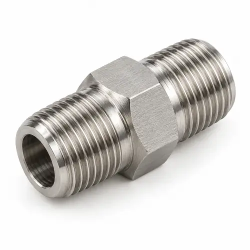
Straight fittings connect components along the same axis. They are commonly used where the hose, tube, or mating component can approach the port directly.
Hydraulic adapters can have different connections at their two ends. This allows equipment with one port standard to connect to a line using another interface.
For custom hydraulic adapters, the two ends should be defined independently. Describing the part only by its overall size leaves the manufacturer without the information needed to produce the correct connections.
Elbows, Tees, and Cross Fittings
Elbows change the direction of a connection. They can help route lines within restricted spaces, provided the arrangement leaves enough room for assembly tools and the required hose bend radius.
Tees and crosses provide branch connections. Their internal passage arrangement needs attention because the external shape does not show how the drilled holes meet inside the body.
For machined parts, passage intersections affect tool access, burr removal, and inspection. A design with several side ports may require additional machining operations even when the outside shape appears simple.
Reducers, Bulkhead Fittings, Plugs, and Caps
Reducers connect different nominal sizes. Their internal passage should be selected for the intended flow requirements rather than reduced simply to make the body easier to machine.
Bulkhead fittings pass through a panel or support and are secured in position. Panel thickness, usable mounting length, and access to the retaining hardware all influence the design.
Plugs and caps close unused ports or line ends. They still require a compatible sealing interface and an appropriate operating rating; being a closing component does not make their connection requirements less important.
Hydraulic Hose Fittings
Hydraulic hose fittings attach a hose to another component. Crimped designs use controlled deformation to secure the fitting to the hose. Reusable designs use a different assembly arrangement and are intended for specified hose constructions.
The hose, fitting, and assembly method must be compatible. A hose fitting cannot be selected solely because its opening appears to match the hose diameter.
When ordering custom hose-end components, the hose attachment geometry and assembly requirements need to be established as part of the design.
Hydraulic Swivel Fittings
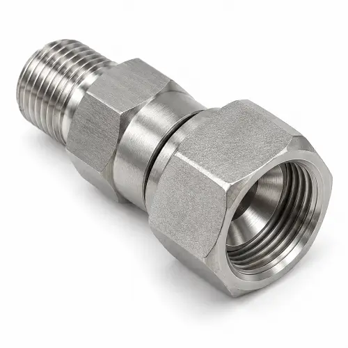
Hydraulic swivel fittings can make installation easier by allowing the connection to be tightened without twisting the hose.
However, an assembly swivel and a connection designed to rotate during operation serve different purposes. Equipment that requires movement under pressure needs a suitable live swivel or rotary connection, with operating limits appropriate to the application.
For a custom part, specify whether the connection only needs adjustment during assembly or must move while the machine is running.
What Are the Common Hydraulic Fitting Connection Types?
The connection standard affects thread geometry, sealing features, and the mating component. Similar thread diameters do not establish interchangeability.
| Connection type | Main identifying feature | Sealing arrangement | Important selection point |
|---|---|---|---|
| JIC | Straight threads and a 37-degree flare seat | Contact between mating flare surfaces | Match the seat geometry as well as the thread |
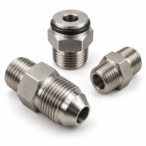
| ORFS | Flat face with an O-ring groove on the male end | O-ring compressed against the mating face | Specify the groove, seal, and mating face |
| SAE O-ring boss, or ORB | Straight threads and an O-ring near the base of the male end | O-ring seals against the matching port geometry | Confirm the port design and seal specification |
| NPT | Tapered pipe threads | Threaded joint with an appropriate sealing method | Confirm thread specification and assembly requirements |
| BSPP | Parallel pipe threads | Separate seal, such as a washer, O-ring, or mating cone | Identify the complete connection design |
| BSPT | Tapered pipe threads | Threaded joint using the specified sealing method | Match the thread form and connection requirements |
JIC stands for Joint Industry Council. Its 37-degree flare seat distinguishes it from other connections that may use similar-looking straight threads.
BSPP and BSPT also need to be distinguished. BSPP uses parallel threads, while BSPT uses tapered threads. The sealing arrangement must match the specific connection.
Likewise, “SAE fitting” is not a complete manufacturing description. A custom drawing should identify the particular interface rather than relying on a broad family name.
How Do Hydraulic Fittings Seal?
Hydraulic fittings may seal through mating metal surfaces, an elastomeric seal, or a threaded joint. Understanding where the seal forms helps identify which features need close attention during design and machining.
Metal-to-Metal Seals
In a JIC connection, the threads bring the mating flare surfaces together. The seal forms at those surfaces.
This makes seat geometry, surface condition, and alignment important. A correctly machined thread cannot compensate for a damaged or incorrectly formed sealing seat.
On a custom fitting drawing, the seat should be defined clearly enough to manufacture and inspect. Specifying only the thread leaves a critical part of the connection unresolved.
O-Ring Seals
ORFS and ORB connections both use O-rings, but the rings occupy different positions and work against different mating features.
The seal needs controlled compression in the assembled connection. Groove dimensions, mating clearances, and edge conditions affect whether the ring remains supported and undamaged.
For machined components, O-ring groove design should follow the selected seal and connection requirements. A groove should not be sized by copying the relaxed ring shape or choosing dimensions that are merely convenient to machine.
Seal material also matters. The metal fitting may be suitable for the fluid while an incompatible O-ring deteriorates in service.
Thread-Sealed Connections
Tapered pipe connections such as NPT use the threaded joint as part of the sealing arrangement. They normally require an appropriate sealant and the specified assembly procedure.
Straight-thread connections that seal at an O-ring, cone, or face work differently. Applying pipe-thread sealant to them does not correct an incorrect or damaged sealing feature.
The practical question is therefore not simply whether the fitting has threads. It is where the design is intended to stop fluid from escaping.
How Do You Identify and Measure Hydraulic Fittings?
Hydraulic fitting identification requires the connection shape, thread measurements, and sealing features to be considered together.
Start by identifying the male or female configuration and whether the threads are straight or tapered. Then locate the sealing feature: a cone, flat face, O-ring groove, shoulder seal, or tapered threaded section.
The main measurements include:
- Thread diameter and pitch.
- Sealing seat or groove geometry.
- Connection length and shoulder position.
- Internal passage diameter.
- Overall dimensions and wrench access.
A nominal fitting size is not necessarily the measured thread outside diameter. For example, a 1/4-inch NPT designation does not mean the external thread measures 1/4 inch across.
For custom hydraulic fittings, these measurements are most useful when documented in a dimensioned drawing with the applicable connection specifications. A CAD model shows the shape, but thread and sealing details still need clear definition.
If a sample is used as a reference, distinguish intended dimensions from wear or damage. An existing part can help establish the design, but a worn sealing face should not become the manufacturing target.
How Do You Choose the Right Hydraulic Fitting?
The right fitting must satisfy the connection requirements, operating conditions, and available installation space. Choosing only by material or thread size can leave other important requirements unresolved.
Match the Connections at Both Ends
Identify what each end connects to and how that interface seals. Include the connection family, size, male or female configuration, and relevant mating geometry.
This is particularly important for custom adapters. One end may connect to an equipment port while the other connects to a hose or tube assembly. Each interface must work with its own mating component.
A hydraulic fittings manufacturer needs the complete interface definition to produce the part correctly. A description such as “threaded adapter with an O-ring” is too broad to establish the finished geometry.
Select Materials for the Actual Environment
Carbon steel, stainless steel, and brass are used in hydraulic fittings, but their suitability depends on the particular design and operating conditions.
Carbon steel fittings are used in many industrial hydraulic applications. Where corrosion protection is needed, the specified coating must suit the environment and be accounted for in the finished dimensions.
Stainless steel hydraulic fittings may be selected for exposure to moisture, washdown, or corrosive conditions. The grade still needs to match the application; specifying stainless steel alone does not establish fluid compatibility or pressure capability.
Brass can suit certain connection applications, but it should be chosen against the required strength, fluid compatibility, and product rating. Ease of machining is not sufficient reason to substitute it for another material.
Consider Pressure, Temperature, and Fluid Together
High-pressure hydraulic fittings require a design suitable for the specified duty. Material, body dimensions, connection size, temperature, and loading conditions all contribute to suitability.
There is no single pressure rating that applies to every fitting in a connection family. The complete assembly must stay within the operating limits of its components, including seals and hoses.
For a custom machined fitting, pressure capability must be established through the appropriate design assessment and verification. Producing the drawing dimensions accurately does not, by itself, qualify the part for pressure service.
Allow Space for Assembly and Operation
Check whether the fitting can be installed, tightened, and removed in its final position.
The design should leave access to wrench flats and sufficient space for the mating component. Hose routing must avoid excessive bending, twisting, and side loading.
For custom parts, body length and outlet position can often be adapted to the equipment layout. Those changes should preserve the connection geometry, required wall sections, and access needed for assembly.
Why Do Hydraulic Fittings Leak?
Leakage can come from an incorrect interface, damaged sealing features, unsuitable seals, assembly errors, or loads imposed by the surrounding installation.
The useful starting point is the sealing location. If the design seals at an O-ring or cone, inspecting only the threads will not reveal the whole problem.
| Possible cause | Why it can lead to leakage | What needs attention |
|---|---|---|
| Mismatched connections | Threads may engage while the sealing features do not match | Complete interface specifications |
| Damaged sealing surface | Scratches or deformation interrupt the sealing contact | Seat or face condition |
| Incorrect or damaged O-ring | The seal may not compress correctly or withstand the fluid | Seal size, material, and gland geometry |
| Assembly error | Incorrect tightening or misalignment can damage or leave the seal incomplete | Specified assembly procedure |
| Hose twist or side loading | External forces act on the connection during use | Routing, supports, and connection arrangement |
| Contamination | Chips or debris interfere with sealing or enter the system | Deburring, cleaning, and handling |
More tightening is not a universal remedy. It cannot correct a mismatched interface and may damage an otherwise usable connection.
Before inspecting or disconnecting a hydraulic fitting, isolate the equipment and release stored pressure. Never use a hand to locate a pressurized leak.
Can You Use PTFE Tape on Hydraulic Fittings?
PTFE tape, often called Teflon tape, is not suitable for every connection.
JIC, ORFS, and ORB fittings rely on their designated sealing surfaces or O-rings. Tape on their threads does not repair a defective seal.
For an NPT connection, follow the system’s approved sealant and application requirements. Some hydraulic systems prohibit tape because loose fragments can enter the fluid circuit.
The choice follows the connection design and equipment requirements, rather than a general rule that all hydraulic fittings need sealing tape.
When Do You Need Custom Hydraulic Fittings?
Custom hydraulic fittings are useful when standard products cannot meet the required interfaces, installation arrangement, or component geometry.
A suitable standard part can simplify purchasing and replacement. Custom machining becomes valuable when there is a defined feature that needs to differ.
Special Connection Combinations
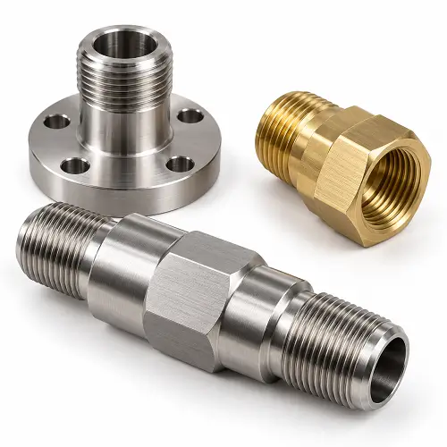
A custom adapter can incorporate different connection standards, sizes, or male and female arrangements at its two ends.
Where possible, established interface geometry can be retained while the body is adapted to the application. This allows the fitting to connect with specified mating components without making every part of the assembly custom.
The design still needs enough material around the threads, passages, and sealing features to meet its requirements.
Custom Lengths and External Profiles
Body length, shoulders, mounting sections, and wrench-flat positions can be machined to suit the equipment layout.
These changes can help when a standard fitting occupies too much space, does not reach the required position, or cannot be secured through the intended support.
The purpose of the change should be clear. A shorter body may improve clearance but also reduce tool access. A longer connection may fit the layout while introducing additional loading that needs consideration.
Special Passages and Mounting Features
Custom machined fittings can include specified through-bores, cross holes, grooves, and mounting features.
Passage dimensions should follow the fluid-system requirements. Enlarging a bore may reduce restriction, but it can also reduce the surrounding wall thickness. Additional side holes introduce intersections that require deburring and inspection.
These relationships should be reviewed before machining, while the design can still be adjusted.
Integrated Adapter Designs
Some assemblies use several separate adapters to achieve the required connection arrangement. A purpose-designed component may combine those functions into one part.
This can reduce separate joints and simplify the layout, provided the integrated design remains practical to manufacture, install, inspect, and service.
For OEM projects, an approved custom drawing also provides a consistent reference for repeat production.
How Are Custom Hydraulic Fittings CNC Machined?
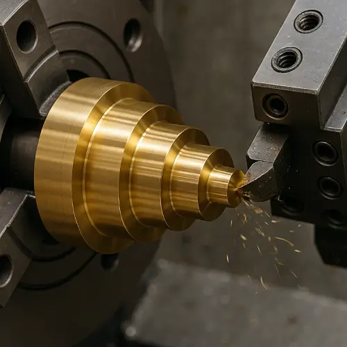
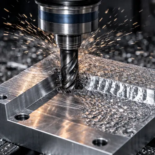
Custom hydraulic fitting machining typically combines turning, drilling, threading, and milling according to the part geometry. The process needs to produce both the visible body and the functional features inside the connection.
At JeekRapid, custom fittings and adapters can be machined from customer drawings, with material, finishing, and inspection requirements reviewed before production.
Turning the Body, Bores, and Connection Ends
CNC turning produces cylindrical features such as outside diameters, shoulders, internal bores, grooves, and many connection ends.
Related features should be machined and checked with their alignment requirements in mind. A thread and sealing seat may each measure correctly in isolation while their relationship still fails the drawing requirement.
Straight adapters can often be produced efficiently from suitable bar stock. More complex bodies may require a different blank or additional machining setups.
Machining Threads and Sealing Features
Threads establish the specified mechanical connection. Seats, faces, and grooves establish the geometry needed for sealing.
These features require separate inspection. Passing a thread gauge does not confirm the condition or geometry of an adjacent sealing face.
When a coating is specified, its effect on the final dimensions needs to be planned before machining. Otherwise, threads or other fitted features that were acceptable before finishing may become unsuitable afterward.
Drilling Passages and Milling Additional Features
Drilling creates the main fluid passages. Further hole machining may be needed where the drawing specifies a more closely controlled bore or surface.
Milling can produce wrench flats, side ports, mounting faces, and other non-cylindrical features. The setup must position these features correctly relative to the connection ends.
For branched passages, machining access and hole intersections deserve attention early in the process. An internal intersection that is difficult to reach may require a different deburring method or a design adjustment.
Deburring, Cleaning, and Inspection
Burrs can remain where drilled passages intersect or where tools break through an edge. Internal burrs are especially important because they may detach and enter the hydraulic circuit.
Deburring should remove unwanted material without damaging sealing edges or altering specified features. Cleaning then needs to remove chips and processing residue from the internal passages as well as the outside surfaces.
Inspection should cover the critical threads, sealing geometry, bores, and dimensional relationships shown on the drawing. Where pressure or leakage testing is required, the method and acceptance criteria must be defined separately from dimensional inspection.
Conclusion
Hydraulic fittings need compatible connections, suitable sealing features, and a design that matches the operating conditions. For custom parts, body shape, passage geometry, mounting requirements, and machining quality all contribute to whether the fitting works in the finished assembly.
When standard fittings cannot provide the required connection combination or installation arrangement, a custom machined component may offer a practical solution.
JeekRapid provides CNC machining for custom fittings and adapters, from prototype parts to production quantities. Send your drawing for a machining review and quote so we can evaluate the connection features, manufacturing requirements, and quantity for your project.