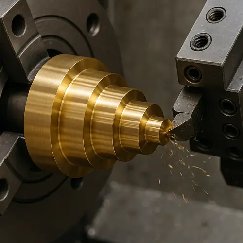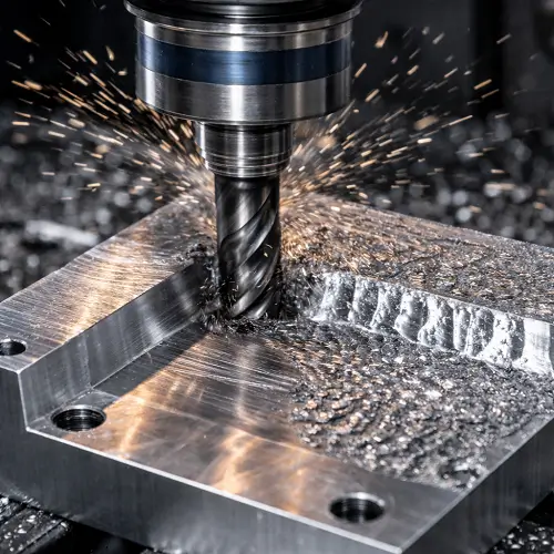
An O-ring groove must compress the seal enough to stop leakage while leaving room for the elastomer to spread and change with pressure and temperature. In a CNC machined part, groove depth, width, surface finish, edge condition, and the mating geometry all affect whether the seal works. A groove can measure correctly and still leak if these conditions are reviewed separately.
This matters in manifolds, valve bodies, pumps, sealed enclosures, plugs, pistons, and other fluid-control components. Designers do not need to become sealing specialists to prepare a machinable part, but they do need to identify the seal type, use the correct O-ring data, and control the features that determine installed compression.
What Is an O-Ring Groove?
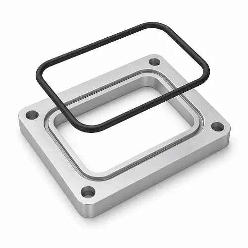
An O-ring groove, also called an O-ring gland, is the machined space that holds an O-ring in position. When the mating parts come together, they reduce the available gland height and compress the O-ring. The elastic seal then contacts both surfaces and closes the potential leakage path.
The groove is only one part of the gland. The groove, mating surface, and clearance between the assembled components work together to confine the O-ring. This is why selecting a ring and cutting a channel with approximately the same shape is not enough. The finished assembly has to provide controlled compression without trapping the seal in a space that is too small.
Standard O-ring sizes and gland recommendations are available through systems such as AS568 and ISO 3601. ISO 3601-2 covers many general hydraulic and pneumatic applications, but pressure, motion, temperature, fluid compatibility, and special service conditions still need application-specific review.
Face Seal vs Radial Seal: What Is the Difference?
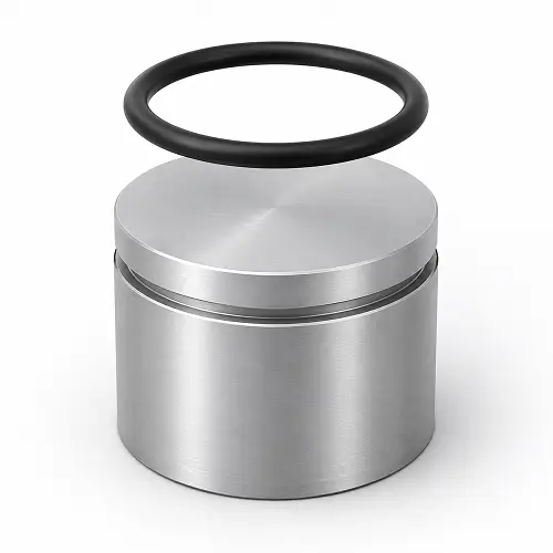
A face seal compresses the O-ring axially between two mating faces. It is common in CNC machined covers, flanges, manifold plates, and enclosure lids. A radial seal compresses the O-ring between an inside and outside diameter, such as a plug inside a bore or a piston moving inside a cylinder.
| Design point | Face seal | Radial seal |
|---|---|---|
| Compression direction | Axial, between two faces | Radial, between a shaft and bore |
| Common CNC parts | Covers, flanges, manifolds, enclosures | Plugs, pistons, shafts, cylindrical housings |
| Main machining concern | Groove depth and mating-face flatness | Diameter, concentricity, and tool access |
| Main assembly risk | Uneven compression around the seal | Cutting or twisting the O-ring during insertion |
The seal type should be chosen before the groove is dimensioned. A static enclosure cover and a moving piston may use an O-ring with the same nominal cross-section, but their gland requirements are not interchangeable. Face seals depend heavily on cover flatness and even compression. Radial seals require attention to friction, surface condition, and how the ring passes over ports, threads, or shoulders during assembly.
How Do You Calculate O-Ring Groove Dimensions?
O-ring groove dimensions start with the actual O-ring size, not with an arbitrary slot. The cross-section, inside diameter, and manufacturing tolerances of the selected ring are used with the seal type and application conditions to determine the groove depth and width.
Groove depth controls the installed gland height and therefore has a direct effect on O-ring squeeze. Groove width provides space for the ring to spread sideways when compressed. The width must also allow for volume changes caused by temperature or fluid absorption. Making the groove narrower does not necessarily make the seal tighter; it can leave the O-ring with nowhere to move.
The nominal CAD dimensions are only the beginning. Check the limits of O-ring cross-section, groove depth, mating gap, shaft or bore diameter, and coating buildup. Do not copy a universal chart without confirming its application. Use gland data for the relevant face, piston, rod, static, or dynamic condition, and involve the seal manufacturer when service conditions fall outside ordinary use.
What Are O-Ring Squeeze and Gland Fill?
O-ring squeeze is the reduction in the seal’s cross-sectional height after assembly. If the original cross-section is known, the basic relationship is:
Squeeze (%) = (O-ring cross-section − installed gland height) / O-ring cross-section × 100
The input values are not fixed. The O-ring cross-section has a manufacturing tolerance, while gland height changes with groove depth, mating dimensions, and assembly gap. Check minimum and maximum conditions instead of nominal dimensions alone.
Too little squeeze may allow leakage. Too much can increase assembly force, friction, and compression set or damage the seal during installation. The correct range depends on static or dynamic use, ring material, and service conditions, so one percentage should not be applied to every design.
Gland fill describes how much of the groove volume is occupied by the O-ring. The seal needs free space to change shape and possibly expand with heat or fluid exposure. Too much fill can pinch the ring or force it toward a clearance gap; too little may reduce stability. Check fill and squeeze together because making a groove shallower changes both.
What Tolerances Do CNC O-Ring Grooves Need?
The most important tolerance is usually the one that controls installed squeeze. For many face-seal grooves, that makes groove depth more functionally sensitive than groove width. For radial seals, the final relationship between the groove diameter, shaft, and bore also determines gland height.
This does not mean every groove needs the tightest tolerance a CNC machine can hold. Groove width can often be more forgiving if gland fill and retention remain correct. Unnecessary precision adds machining and inspection cost without improving the seal.
Flatness matters on a face seal because the cover and body must compress the O-ring consistently around the full path. A groove may pass width and depth inspection while a distorted cover, unstable thin wall, or widely spaced fasteners allow part of the joint to open. In a radial seal, bore roundness, shaft size, and concentricity may be more important than an exceptionally tight groove-width tolerance.
Inspection must match the callout. An open face groove is usually easier to measure than a narrow internal groove, which may require a dedicated gauge or specialized probe. A tolerance that cannot be verified reliably is not a useful production requirement.
What Surface Finish Is Required for an O-Ring Groove?
An O-ring groove and its mating surface need a controlled finish without scratches, tears, chatter, or burrs that cross the sealing path. A low average roughness value does not guarantee a leak-free surface if one deep scratch creates a continuous channel under the seal.
Static seals are generally more forgiving than dynamic seals because the O-ring does not slide repeatedly against the surface. In a moving piston or rod seal, roughness, tool-mark direction, lubrication, and hard edges affect friction and wear. The shaft or bore finish can be more critical than the groove bottom itself.
The drawing should identify which surface actually seals and where its finish callout applies. The guide to surface finish vs surface roughness explains why appearance and an Ra value do not always describe the same condition. Avoid uncontrolled hand polishing because it can roll edges or change groove depth locally.
How Are O-Ring Grooves Machined?
Face-seal grooves are commonly milled into a flat CNC machined surface. Circular grooves can be interpolated with an end mill or produced with suitable groove tooling. Non-circular sealing paths can also be milled, but small inside radii, abrupt direction changes, and narrow sections may require smaller, less rigid cutters.
External radial grooves on shafts are usually straightforward to produce on a CNC lathe because the cutting area is visible and accessible. Internal grooves are more difficult. The grooving bar has to reach inside the bore, and extra overhang reduces rigidity. Tool access, chip clearance, groove location, and the ability to measure the feature all affect cost and consistency.
Groove geometry should reflect real tool access. A deep, narrow groove requires a less rigid tool, while an internal groove close to a shoulder may not leave room for the cutting edge and holder. A sharp internal corner in CAD will also become a tool radius unless another process is specified.
Quantity also matters. Standard tools are often economical for prototypes, while a form tool may improve consistency in repeat production. The choice depends on profile, tolerance, material, access, and inspection.
Why Do O-Ring Grooves Leak?
An O-ring groove can leak even when its width is within tolerance. Leakage often comes from the assembled sealing system rather than one isolated dimension.
Incorrect groove depth is a common cause. A groove that is too deep may not provide enough squeeze, while a shallow groove may overcompress the seal. An incorrect groove width can create excessive gland fill and leave too little room for the elastomer to spread.
Surface damage is another common problem. A scratch across the contact path may form a direct leakage channel. Burrs and sharp entry edges can cut the O-ring as it is installed, especially when a radial seal passes over a port, thread, or shoulder. The damage may not be visible once the parts are assembled. Controlled deburring and an appropriate lead-in chamfer reduce that risk, but the chamfer must not remove part of the required sealing land.
On face seals, poor mating-surface flatness or uneven bolt loading can reduce compression locally. Adding more squeeze to the groove does not necessarily correct a flexible cover. The cover thickness, fastener spacing, pressure direction, and support around the seal may need to be reviewed together.
The O-ring itself may also be wrong. An incorrect cross-section changes squeeze and fill, while an incompatible elastomer may swell, harden, or lose sealing force. CNC machining cannot compensate for a seal selected without considering fluid and temperature.
Surface treatment is easy to overlook. Anodizing, plating, and other coatings can change final groove dimensions, edge condition, and mating surfaces. The amount and direction of dimensional change depend on the process, so a single coating allowance should not be applied to every finish. Critical groove dimensions should be defined in the required final condition, with masking or machining compensation agreed before production.
How Do You Design an O-Ring Groove for CNC Machining?
Begin with a standard O-ring that suits the fluid, temperature, pressure, and motion. Then design the groove from the published gland data for that application. This is usually more reliable and less expensive than creating a custom cross-section or adjusting a groove around whatever space remains in the CAD model.
Keep the feature accessible. A wider tool is more rigid than a very thin one, and an external or open-face groove is easier to machine and inspect than a deep internal groove. If the seal must sit in a bore, leave room for the grooving bar to enter, cut, retract, and clear the shoulder.
Provide realistic corner radii and a controlled assembly lead-in. A radial O-ring should not scrape across a sharp edge, exposed thread, or unchamfered port. At the same time, an oversized chamfer can reduce the supporting land or create too much clearance near the seal. The entry geometry should guide the O-ring without weakening the gland.
Keep sealing grooves away from thin, flexible walls when possible. Cutting the groove removes material, and tightening the mating part applies additional load around it. A thin cover or wall can distort enough to change compression even if the groove itself is accurately machined. The design of CNC machined enclosures often depends on this relationship between the groove, cover stiffness, alignment features, and fastener layout.
Define tight controls only where they protect sealing function. Groove depth, sealing-surface condition, and mating geometry may deserve close control; unrelated exterior dimensions usually do not. This concentrates machining and inspection effort on features that can actually cause leakage.
What Should Be Included on an O-Ring Groove Drawing?
A 3D model shows the groove shape, but it does not fully explain how the seal will be used. The 2D drawing should identify the selected O-ring size or standard, whether the seal is face or radial, and whether it operates in static or dynamic service.
Dimension the groove width, depth, diameter or path, corner radii, and required tolerances. Identify the sealing surface and apply any surface-finish, flatness, roundness, or concentricity control only where it is functionally needed. For a radial assembly, show the insertion chamfer and any ports or edges the O-ring must cross.
Also state the material, coating or anodizing requirement, and whether dimensions apply before or after finishing. Provide the fluid, pressure, temperature, motion, O-ring material, and any required inspection record when they affect acceptance. This lets the CNC supplier review tool access, wall stability, deburring, finishing allowance, and measurement before machining.
A CNC-Machined O-Ring Groove Review Example
Consider an anodized aluminum enclosure with a face-seal groove. The first drawing review shows that the groove width is within the selected machining tolerance, but width alone does not confirm that the enclosure will seal. The installed result also depends on groove depth, O-ring cross-section, cover flatness, fastener spacing, sealing-surface condition, and the final anodized dimensions.
In a practical JeekRapid review, the O-ring specification, squeeze, and gland fill would be checked at their tolerance limits. The groove entrance and sealing path would be reviewed for burrs and tool marks, while the cover and fastener layout would be checked for even compression. The drawing would also clarify the required post-anodizing condition.
This review may show that the groove does not need to become tighter everywhere. The better solution may be to control groove depth more clearly, improve the assembly lead-in, strengthen the cover, adjust fastener placement, or define the post-finish condition. That is the practical reason to review the seal as an assembly rather than approving the groove from one measured width.
Conclusion
Reliable O-ring groove design is not based on groove width alone. The selected seal, squeeze, gland fill, groove depth, mating geometry, surface condition, assembly edges, and final coating all influence whether a CNC machined part seals consistently.
Use recognized O-ring and gland data as the starting point, then apply tolerances to the features that control actual function. If a manifold, valve body, enclosure, plug, piston, or fluid-control part contains an O-ring groove, upload the CAD file and 2D drawing to JeekRapid. Include the O-ring specification, material, coating, pressure, temperature, and critical inspection requirements for a free DFM review and quote within 24 hours.