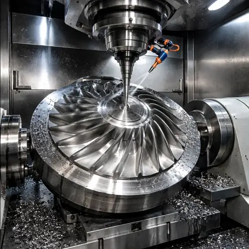
Blisk machining for aerospace engines is fundamentally a 5-axis CNC problem.
The component combines twisted airfoil geometry, thin structural sections, high-strength alloys, and extreme accuracy requirements into a single rotating part. Without continuous 5-axis control, stable production of aerospace blisks is not realistically achievable.
In real manufacturing work, the difficulty of blisk machining does not come from any single feature. The challenge comes from the interaction between geometry, material behavior, thermal distortion, vibration, cumulative error, and dynamic balance — all acting on one component that must remain stable at operating speed.Aerospace blisks belong to a broader family of high-precision rotating components.
Similar 5-axis machining challenges also appear in impeller machining and turbine blade machining, where complex airfoil geometry and tight tolerances dominate the manufacturing process.
What Is an Integrally Bladed Rotor (Blisk)?
A blisk, or bladed disk, is a rotor where the blades and hub are manufactured as one continuous structure.
Removing mechanical joints reduces weight and improves aerodynamic efficiency, but it also removes the ability to replace individual blades, increasing manufacturing risk and repair complexity.
Modern aerospace engines increasingly rely on blisks in compressor and fan stages where rotational loads, temperature gradients, and aerodynamic stability leave little margin for manufacturing error.
Blisk Machining Process Steps
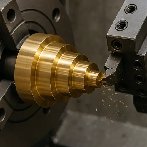
Material Preparation and Stress Stabilization
Aerospace blisks usually start from forged or billet stock made from titanium alloys or nickel-based superalloys.
Without proper stabilization at this stage, internal stresses release during cutting and introduce distortion that cannot be fully corrected later.
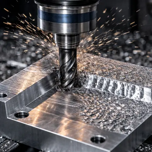
5-Axis Rough Machining
Roughing removes most of the excess material while maintaining balanced thermal conditions across the rotor.
On large compressor blisks, the total blade span can exceed 20 in, while final dimensional accuracy is still expected to remain extremely tight. That contrast between size and tolerance is one of the core manufacturing difficulties.
Semi-Finishing of Airfoil Geometry
Semi-finishing defines blade thickness distribution and hub transitions while leaving controlled stock for final finishing.
Precision Finishing of Blades and Hub
Final finishing determines blade-to-blade consistency and surface integrity.
Post-Machining Stabilization and Micro-Finishing
Depending on program requirements, controlled stabilization and micro-finishing may be applied before final inspection and balancing.
Core 5-Axis CNC Requirements for Blisk Machining
True 5-axis motion is required to maintain correct tool orientation along twisted airfoil surfaces and into confined blade-root regions.
In blisk production, axis synchronization error shows up immediately as surface waviness, local profile deviation, or blade-to-blade inconsistency.
Tool axis orientation must remain stable as the cutter transitions from the airfoil surface into the blade root.
Even small misalignment at this transition generates local stress concentration and accelerates tool wear, especially when machining titanium or nickel-based alloys.
Consistent blade-to-blade geometry is mandatory.
When variation between blades increases, aerodynamic loading becomes uneven and dynamic balance deteriorates, reducing both efficiency and service life.

Precision and Inspection Control in Aerospace Blisk Production
Dimensional control of a blisk extends far beyond basic feature measurement.
Full airfoil scanning and blade profile mapping are required to confirm that the final geometry matches the designed aerodynamic surface.
Runout verification is equally critical.
Excessive radial or axial runout introduces imbalance that amplifies vibration at operating speed and increases bearing load inside the engine.
In many aerospace programs, inspection feedback is used to refine finishing passes and adjust machining parameters, making measurement and machining a tightly coupled process rather than two separate steps.
Common Problems in Blisk Machining
5-Axis Control Limitations
Blisk geometry forces continuous 5-axis motion across twisted airfoil surfaces and deep blade-root regions.
Any instability in 5-axis synchronization immediately appears as surface deviation and inconsistent blade geometry.
Thermal Distortion
Heat buildup during roughing and semi-finishing causes local expansion in both blades and hub.
Once thermal distortion appears, recovering final geometry becomes extremely difficult during finishing.
Cumulative Geometric Error
Small deviations introduced at each stage of machining accumulate across the entire rotor.
On many compressor blisks, overall profile accuracy is typically held within ±0.001 in, and on high-pressure stages this limit is often tightened even further.
Spindle Vibration and Tool Stability
Long-reach tooling, thin blade sections, and deep cutting engagement amplify spindle vibration.
If vibration is not tightly controlled, both surface integrity and dimensional accuracy degrade quickly.
Blade-to-Blade Consistency
Even minor variation between blades disrupts aerodynamic loading and directly reduces engine efficiency.
Maintaining blade-to-blade consistency is one of the hardest problems in blisk manufacturing.
Dynamic Balance Risk
Because blades and hub are machined as a single structure, any local error affects the balance of the entire rotor.
Loss of dynamic balance increases bearing load, vibration, and long-term reliability risk.
Conclusion
Blisk machining for aerospace engines leaves little margin for error.
When 5-axis control, thermal behavior, vibration suppression, and geometric consistency are managed correctly, blisks deliver the aerodynamic efficiency and mechanical stability modern engines demand.
When any of these elements drift out of control, performance loss and scrap risk increase quickly.
In many projects, a short process review before cutting begins prevents far more cost and delay than any correction attempted on the shop floor.
For aerospace blisk programs requiring stable geometry, consistent blade quality, and repeatable machining results, JeekRapid supports production through dedicated 5-axis CNC capability, disciplined process control, and inspection systems aligned with aerospace manufacturing requirements.