Tool chatter starts when the cutting system loses stability.
In practical terms, the tool, machine, and workpiece stop behaving like a rigid structure and begin vibrating against each other. Once that vibration becomes self-exciting, surface finish degrades, tool life drops, and dimensional accuracy becomes difficult to hold.
On the shop floor, chatter rarely appears without warning. A CNC job becomes louder, the spindle tone changes, surface patterns start to look uneven, and operators begin compensating with feed and speed adjustments. By the time chatter is clearly visible on the part, productivity and consistency are already compromised.
Anyone who has chased chatter on a real machine recognizes this moment immediately. The key is understanding what conditions allow chatter to form, so the process can be stabilized before scrap, rework, and tool failure begin to dominate the job.
What Is Chatter in Machining?
In machining, chatter is a self-excited vibration created by the interaction between cutting forces and the natural frequencies of the machine–tool–workpiece system. Unlike simple vibration from imbalance or looseness, chatter feeds on itself. Each cutting pass leaves behind surface waviness, and the next pass amplifies it. Instead of dying out, the vibration grows.
Definition of Tool Chatter
In practice, tool chatter is what happens when the cutting force and the surface left behind by the tool begin feeding each other. The tool cuts a wavy surface, the next pass reacts to that waviness, and the vibration grows instead of fading. Once that loop starts, the process becomes unstable very quickly.
Common Types of Machining Chatter
Although chatter appears as a single problem on the shop floor, it develops through different vibration mechanisms.
Regenerative Chatter
This is the most common and most destructive form. Surface waviness from one pass changes the cutting force on the next. That force change increases vibration, which deepens the waviness. The cycle accelerates quickly and becomes difficult to stop once it starts.
Forced Vibration Chatter
This form originates outside the cutting process itself — spindle imbalance, bearing defects, misalignment, or even vibration from nearby equipment. If the system lacks damping, these external vibrations get amplified during cutting.
Mode Coupling Chatter
Mode coupling appears when multiple vibration modes interact. It is often seen on thin-walled parts, flexible setups, and complex geometries where several natural frequencies lie close together.
Why Chattering Occurs in CNC Machines
Chatter does not begin with a single bad setting. It develops when the cutting system gradually loses stability. Something becomes too flexible, cutting forces fluctuate, and vibration that should fade instead grows.
Insufficient Tool and System Rigidity
Long tool stick-out, small cutter diameter, and flexible holders reduce stiffness more than most operators realize. Once the tool bends under load, cutting forces fluctuate and vibration builds quickly.
Weak Workholding and Part Support
If the part can move, chatter will follow. Thin walls, poor clamping, and insufficient backing allow the workpiece to deflect during engagement. Many chatter problems disappear the moment the part is properly supported.
Unstable Cutting Parameters
Certain spindle speeds and feeds line up with the natural frequencies of the system. When that happens, vibration increases instead of fading. Small changes in speed often make a dramatic difference.
Low Machine Structural Damping
Machines with worn ways, loose joints, or aging spindle components struggle to absorb vibration energy. Without sufficient damping, even moderate cutting forces can trigger chatter.
Tool Wear and Edge Damage
As tools wear, cutting forces become inconsistent. This irregular loading lowers the stability margin and often turns a previously stable setup into an unstable one.
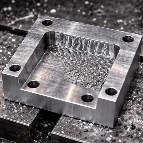
Chatter Marks and Surface Finish Problems
Chatter leaves visible surface defects known as chatter marks — repetitive ripples or wave patterns that reduce dimensional accuracy, fatigue life, and part reliability.
In real CNC production, chatter usually appears in surface finish before it causes dimensional failure. A stable cut on aluminum or steel often produces surface roughness around Ra 32–63 μin, while the same operation with developing chatter can quickly degrade to Ra 125 μin or worse. On sealing faces, bearing surfaces, and cosmetic parts, this surface damage alone is often enough to scrap the part even if dimensions remain within tolerance.
Once chatter grows, flatness, parallelism, and roundness errors usually follow.
How to Reduce Tool Chatter in CNC Machining
Increase Rigidity Across the Cutting System
If chatter appears, start by making the cutting assembly as stiff as possible. Shorten tool overhang, use a larger diameter cutter when possible, upgrade the holder, and improve fixturing. These changes raise system stiffness and immediately improve stability.
Optimize Spindle Speed and Cutting Parameters
Shifting spindle speed away from unstable frequency zones often eliminates chatter immediately. In many practical cases, moving the spindle speed by 10–15% is enough to push the process out of resonance without changing tooling or fixturing.
Improve Tool Geometry and Damping
Variable-pitch and variable-helix cutters break harmonic vibration patterns. Damped toolholders further suppress vibration growth in difficult setups.
Maintain Sharp, Consistent Tool Condition
Sharp tools generate stable cutting forces. Worn edges drastically reduce the stability margin and accelerate chatter formation.
Practical CNC Shop Recommendations
In real production, the fastest way to stabilize a chattering process is to walk through the system in this order.
Step 1: Check Tool Rigidity and Overhang
Measure tool stick-out and reduce it as much as the part geometry allows. As a general guideline, keep overhang within three times the tool diameter.
Step 2: Verify Workholding and Part Support
Inspect how the part is clamped. Look for deflection, movement, or vibration when the tool engages. Add supports, clamps, backing plates, or temporary ribs on thin walls before touching cutting parameters.
Step 3: Adjust Cutting Parameters
Once the mechanical setup is stable, fine-tune spindle speed, feed rate, and depth of cut to restore smooth cutting.
Step 4: Inspect Machine Structural Condition
If chatter persists, check for loose fixtures, worn ways, spindle bearing noise, or abnormal vibration that may be reducing damping.
Following this sequence prevents wasted time chasing parameter changes when the real problem is mechanical stability.
CNC Chatter Troubleshooting & CAD Review Support
In many projects, chatter is not caused by cutting parameters alone.
Part geometry, wall thickness, feature depth, and tool reach often determine whether a stable process is even possible.
When chatter becomes difficult to control, a drawing-level review usually reveals the real constraints behind the problem. Tool access, minimum wall sections, corner radii, and feature orientation all influence vibration behavior long before the part reaches the machine.
If your current project is struggling with chatter or unstable surface finish, submitting the part drawing or CAD model allows JeekRapid’s engineers to evaluate the machining risks and recommend a stable cutting strategy before production begins.
Why Choose JeekRapid’s CNC Machining Approach
In real projects, chatter problems usually do not come from one bad tool or one bad machine. They come from an unstable process that was never fully controlled from the beginning.
JeekRapid begins by reviewing tool selection, holder rigidity, and overhang limits during process planning. High-risk geometries such as thin walls, deep pockets, and long-reach features are flagged early so fixture design and cutting strategies can be adapted before production starts.
During process development, JeekRapid’s engineers establish stable spindle speed windows, validate feed per tooth ranges, and control radial and axial engagement to stay within safe vibration limits. Tool wear, surface finish consistency, and dimensional stability are tracked across trial runs to ensure that chatter does not return during long production cycles.
This systematic approach allows JeekRapid to maintain surface quality, extend tool life, and deliver predictable machining results even on difficult materials and complex geometries.
FAQs
What is the most common cause of tool chatter?
Insufficient system rigidity, usually from excessive tool overhang or weak fixturing.
Can increasing spindle speed reduce chatter?
Yes. Increasing speed by about 10–15% often moves the cut out of resonance and reduces vibration.
Does chatter always indicate machine problems?
No. Most chatter originates from tooling, fixturing, and cutting conditions rather than machine faults.
How does chatter affect surface finish?
It can degrade surface roughness from Ra 32–63 μin to Ra 125 μin or worse.
Can tool geometry help prevent chatter?
Yes. Variable-helix and variable-pitch cutters significantly improve chatter stability.