A tapped hole is a threaded hole made with a tap. “Threaded hole” is the broader term: the internal thread can be produced by tapping, thread milling, or another method. For your CNC part, the practical questions are whether the screw fits, has enough usable thread, and clamps the assembly without bottoming out.
If you are ordering a housing, bracket, or mounting plate, you usually do not need to choose between “tapped” and “threaded” as two different hole designs. You need to specify the thread and show what the connection must do. The manufacturing method comes next.
What Is a Tapped Hole?
A tapped hole has an internal thread produced with a tap. The shop first prepares a hole, then uses the tap to create the thread that accepts the screw.
A cutting tap removes material. A forming tap displaces material to form the thread and is suitable only for appropriate materials and applications. These methods require different prepared hole sizes, so the hole diameter should not be chosen without knowing how the thread will be made.
For a typical mounting plate with standard threaded holes, tapping is often a practical production method. However, the word “tapped” alone does not tell the shop the thread size, fit, or depth. A drawing that says only “tapped hole” is still missing the information needed to make it.
What Is a Threaded Hole?
A threaded hole is any hole with an internal thread. Tapped holes belong to this category, along with holes made by thread milling and other thread-producing methods.
Think of an aluminum housing with a removable cover. The screws pass through clearance holes in the cover and engage threaded holes in the housing. The cover holes let the screws pass through; the housing threads hold them.
Whether those housing threads were tapped or thread-milled may make no difference to assembly, provided they meet the same drawing requirements. Calling one hole “threaded” and another “tapped” does not, by itself, make either one stronger or more accurate.
Does Your Part Need Tapping or Thread Milling?
For many custom parts, you can specify the finished thread and let the shop propose how to produce it.
If you need a mounting plate with accessible, standard-size threaded holes, tapping is a reasonable option to discuss. If the material is difficult to machine, the thread is large, or the shop needs more control over thread size, thread milling may be worth considering. Neither method is automatically the best choice for every part.
The useful question is: “Can you produce and inspect this thread in this material, at this depth?”
For example, a shallow threaded hole in an open aluminum plate presents a different problem from the same thread at the bottom of a narrow recess. The second design restricts tool access. Sending the complete part model helps the shop see that difference before quoting.
If your drawing specifically requires tapping, the supplier should discuss any proposed change with you. If only the finished thread matters, avoid adding a process restriction without a reason.
Should You Use a Blind or Through Threaded Hole?
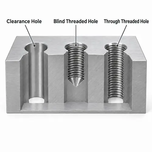
A blind threaded hole stops inside the part. A through threaded hole extends through it.
If a screw must not emerge from the back of an enclosure, a blind hole may suit the design. But there must be enough material for the usable thread, the space needed below it, and the remaining wall thickness. A shallow housing wall cannot accommodate an arbitrarily deep thread.
If the back can remain open, a through hole removes the closed-bottom constraint. You still need to check whether the screw will protrude into a moving component, cable space, or another mating part.
Consider a cover fastened to an aluminum enclosure. A blind hole can keep the fastener opening from breaking into the enclosure interior. A through hole may be acceptable on an external mounting flange, where the back is accessible and screw protrusion causes no interference.
Choose according to the assembly and available material, rather than assuming blind holes are always better.
How Much Thread Depth Does the Screw Actually Need?
Start by separating three dimensions: the drilled hole depth, the usable full thread depth, and how far the screw enters the part. They are not interchangeable.
A blind hole may include a conical drill bottom and incomplete threads near its end. That space is not equivalent to usable full thread. Even a bottoming tap needs clearance; it does not create full threads all the way to the bottom of a drilled hole.
Suppose a screw has an under-head length of 0.750 in and passes through a 0.250 in cover. With no washer or counterbore, it projects 0.500 in into the housing.
That calculation tells you the penetration, not that 0.500 in is automatically a suitable engagement depth. You still need to check the usable thread, bottom clearance, material, and load. A screw can reach the bottom and feel tight while leaving the cover loose.
A shorter screw may prevent bottoming, but it must still provide sufficient engagement for the connection. Simply choosing the longest screw that fits—or shortening it until it turns freely—does not establish that the joint is adequate.
For a drawing review, provide the screw specification and the thickness of the components it passes through. Those details let the supplier check the actual assembly instead of guessing from the hole alone.
How Do You Specify a Tapped Hole on a Drawing?
A useful tapped hole callout identifies the thread, its location, and the required extent of the thread.
For example, 1/4-20 UNC-2B describes an internal Unified coarse thread with a nominal diameter of 1/4 in, 20 threads per inch, and a Class 2B fit. The 1/4 in dimension is not the diameter of the hole to drill before tapping.
For a blind hole, state the required full thread depth separately from any specified drilled depth. If you need 0.500 in of full thread, do not label a 0.500 in drilled hole and assume it means the same thing. The supplier must also check whether the part has enough material for the additional tool clearance.
For a through thread, clearly indicate that the thread passes through. Locate the holes from suitable drawing references so the supplier can check whether they will align with the mating part.
If the part will receive a coating, state whether the thread must meet its specified fit after finishing. Otherwise, a thread that passes inspection before coating may become too tight afterward.
If you only know which screw you will use, send its full specification or manufacturer’s part number. Measuring the screw’s outside diameter alone does not identify its pitch or thread standard.
Why Won’t a Screw Fit a Tapped Hole?
The point at which the screw stops often helps narrow down the problem. Do not immediately assume the hole needs to be tapped deeper.
| What happens during assembly? | What should you check first? |
|---|---|
| The screw will not start | Confirm thread diameter and pitch, then inspect the entrance for burrs, damage, or misalignment. |
| It starts but stops after a few turns | Compare screw penetration with usable thread depth and bottom clearance; check for chips or damaged threads. |
| It fitted before coating but is now tight | Check coating buildup and the specified thread fit after finishing. |
| The screw feels tight but the cover remains loose | Check whether the tip has bottomed out or an unthreaded screw shoulder has reached the hole entrance. |
| Each screw fits separately, but the cover will not assemble | Check hole positions and clearance in the mating component. |
For example, a 1/4-20 screw and a 1/4-28 screw have the same nominal diameter but different pitches. They are not interchangeable. Forcing the wrong screw can damage an otherwise acceptable hole.
If the screw stops before clamping the cover, compare its projecting length with the available space before changing the part. The screw may simply be too long. Drilling deeper without checking the remaining wall could break through the housing.
Burrs in CNC machining can also obstruct the thread entrance. Removing an entrance burr may solve that obstruction, but it will not correct the wrong pitch or a misplaced hole.
For coated parts, do not automatically run a tap through the finished thread. That can remove protective coating and alter the thread. First establish whether the problem comes from coating thickness, contamination, or the underlying thread size.
How Can You Check Threaded Holes Before Parts Are Shipped?
Ask for inspection that addresses how the part assembles.
A suitable thread GO/NO-GO gauge checks thread size against the specified limits when used according to the applicable gauging rules. It does not, by itself, prove that the hole is correctly positioned or that your screw has enough bottom clearance.
For a cover mounted with four screws, the thread size and the four-hole pattern both matter. For a blind hole, usable thread depth matters too. For a coated part, acceptance should address the condition in which you receive and assemble it.
Trying a production screw can help reveal an assembly problem, but one screw turning into the hole is not a substitute for the required thread inspection.
Before placing the order, identify the holes that are critical to assembly and agree on the checks needed. A clear request—such as checking the thread fit after coating and verifying the cover’s hole pattern—is more useful than asking only for “high-quality threads.”
Get CNC Machined Parts with Threads That Fit Your Assembly
When requesting CNC machining from JeekRapid, include your CAD model, drawing, material, quantity, and thread specifications. For blind holes, show the required usable thread depth. Include any surface finishing requirements that could affect the final fit.
If you are unsure about screw length or hole depth, send the mating component details and screw specification with the drawing. If an existing assembly does not fit, explain what happens: the screw will not start, stops halfway, or tightens without clamping. That gives the review a specific problem to resolve before another batch is made.