Shaft couplings connect rotating shafts in motors, pumps, conveyors, and other machinery. Their performance depends on both the coupling design and the quality of its manufactured features. The bores must fit the shafts, the attachment features must hold securely, and the components must work together without introducing unwanted movement or loading.
Shaft coupling machining produces those functional features, including bores, mounting faces, keyways, clamp slots, and threaded holes. For custom parts, the manufacturing approach depends on the coupling type, its connection requirements, and whether the order covers an individual hub or a complete assembly.
What Is a Shaft Coupling?
A shaft coupling joins two shafts so that one can transmit rotation and torque to the other. One shaft is usually connected to a motor or drive, while the other connects to the equipment being driven.
A shaft coupler may connect shafts of the same diameter or different diameters. Its ends secure the shafts through features such as clamps, set screws, keys, or splines.
Between those connections, the coupling can have a solid body or a structure that allows controlled movement. A rigid coupling maintains a direct connection between aligned shafts. A flexible coupling uses an elastic element, sliding component, or flexible metal section to accommodate specified misalignment or movement.
The coupling normally works alongside the bearings that support the shafts. It should not be used to force poorly aligned shafts into position.
What Are the Different Types of Shaft Couplings?
Different shaft coupling types solve different problems. Some prioritize a stiff connection, while others accommodate shaft offset, reduce transmitted vibration, or support accurate positioning.
The following are common types relevant to CNC machined coupling bodies and hubs.
Rigid Shaft Couplings
Rigid shaft couplings connect shafts without a flexible element designed to accommodate misalignment. They suit arrangements where the shafts can be accurately aligned and remain aligned during operation.
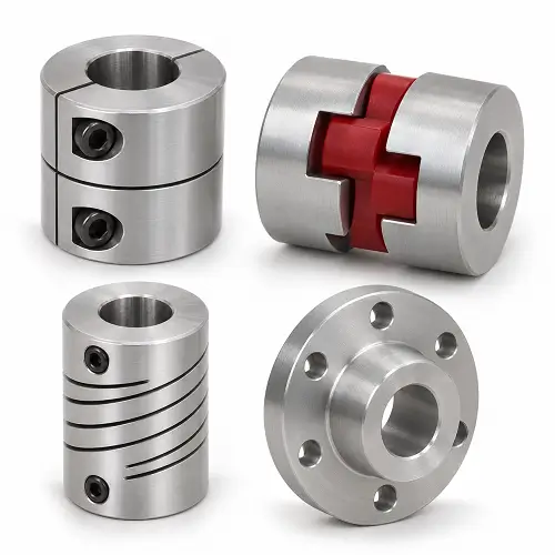
Common structures include sleeve, split clamp, and rigid flange couplings.
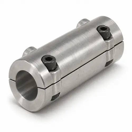
A sleeve coupling surrounds the shaft ends with a cylindrical body. Depending on the design, keys, set screws, or other features secure the shafts inside it.
A split clamp coupling closes around the shafts when its screws are tightened. A two-piece design can be assembled around the shafts, which is useful when the shafts cannot easily be moved axially.
A rigid flange coupling connects two shaft-mounted hubs through mating flanges and fasteners. The flange faces, locating features, and bolt pattern determine how the two halves assemble.
The advantage of a rigid connection is high torsional stiffness without a compliant intermediate element. Its limitation is that shaft misalignment can create unwanted loads in the connected shafts and bearings.
For machining, the main concerns are the relationship between the bores, the mounting faces, and the shaft attachment features. A bore can be the correct diameter yet still cause problems if its axis is incorrectly positioned.
Jaw Couplings
A jaw coupling generally has two metal hubs with projecting jaws and an elastomeric insert between them. The insert, often called a spider, transfers load between the hubs.
The elastomer can cushion shock and damp vibration, making this design useful in many motor-driven applications. Its material also affects temperature resistance, chemical compatibility, and torsional stiffness.
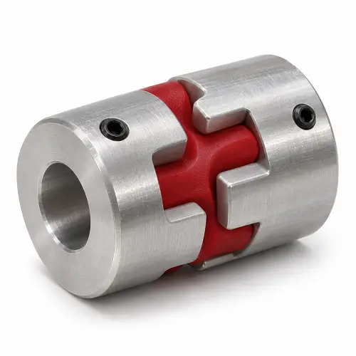
A softer or more compliant insert may provide useful damping, but it also allows more elastic movement under load. Positioning applications therefore need attention to both backlash and torsional stiffness. Ordinary jaw couplings should not automatically be treated as zero-backlash designs.
The machined components are usually the metal hubs. Their bores, jaws, keyways, and fastening features must match the approved assembly design. The spider is a separate component with its own material and geometry requirements.
Making the hubs from a stronger metal does not automatically increase the complete coupling’s capacity. The insert or another part of the assembly may still be the limiting component.
Beam Couplings
Beam couplings are commonly made from one piece of metal with engineered helical or other slot patterns through the body. The remaining material forms flexible sections that transmit torque while accommodating limited shaft misalignment.
Their compact structure makes them relevant to encoders, instrumentation, and smaller motion-control assemblies, depending on the specific design.
The slot pattern controls how the coupling behaves. A part with longer or thinner flexible sections may accommodate movement differently from one with shorter or thicker sections, even when their outside dimensions are similar.
Beam couplings are therefore a direct example of machining geometry affecting mechanical performance. Slot width, spacing, remaining section thickness, and edge condition all matter.
A custom beam coupling needs an engineered drawing. Copying the visible cuts from a photograph is not enough to establish torque capacity, stiffness, or fatigue life.
Oldham Couplings
An Oldham coupling uses two hubs and an intermediate disc. Features on opposite sides of the disc engage with the hubs and permit sliding movement as the assembly rotates.
This structure is particularly useful when parallel shaft offset is an important selection requirement. The disc moves relative to the hubs instead of relying entirely on bending a metal element.
The center disc material influences wear, stiffness, and backlash behavior. Because sliding occurs during operation, access for disc inspection or replacement can also matter.
The coupling still has limits for angular misalignment, axial movement, speed, and torque. Its ability to accommodate parallel offset does not make it suitable for unrestricted movement.
Machining focuses on the shaft bores, fastening features, and the hub geometry that engages the center disc. That interface needs the specified fit: excessive clearance can introduce lost motion, while an unsuitable tight fit can interfere with sliding.
Disc Couplings
Disc couplings transmit torque through thin metal discs or disc packs connected to hubs. The discs flex in controlled directions while remaining relatively stiff in torsion.
They can suit applications where rotational response matters and a flexible metal connection is appropriate.
A single-disc arrangement and a double-disc arrangement do not accommodate movement in the same way. Parallel offset generally requires the appropriate arrangement of separated flexible sections rather than simply adding flexibility to one location.
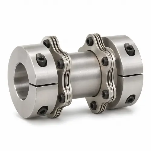
The machined hubs, spacers, locating features, and bolt holes must match the disc-pack design. Their alignment and assembly geometry affect how loads pass through the coupling.
Disc packs and fasteners also form part of the performance specification. Accurately machining the hubs alone does not establish the rating of the completed assembly.
Bellows Couplings
Bellows couplings connect two hubs through a thin-walled, corrugated metal element. The bellows accommodates specified movement while providing high torsional stiffness.
This combination makes the design relevant to precision positioning and other motion-control applications.
The bellows is sensitive to excessive stretching, compression, and misalignment. Installation space and the specified distance between the hubs need to be respected.
CNC machining normally produces the hubs and their attachment interfaces. The bellows is manufactured separately and joined to the hubs using the specified assembly method.
For a custom order, the hub geometry, bellows specification, and joining requirements must be considered together. A thicker hub cannot compensate for a bellows that is unsuitable for the operating duty.
How Do These Coupling Types Compare?
| Coupling type | Main reason to consider it | Important limitation | Typical machined features |
|---|---|---|---|
| Rigid | Direct, stiff connection between accurately aligned shafts | Does not provide designed misalignment compensation | Bores, faces, keyways, clamp slots, flanges |
| Jaw | Shock cushioning and vibration damping | Performance depends strongly on the insert and assembly design | Hub bores, jaws, fastening features |
| Beam | Compact flexible connection | Slot geometry affects stiffness, load capacity, and fatigue | Bores, engineered slots, clamp features |
| Oldham | Accommodation of parallel offset | Sliding disc introduces wear and fit considerations | Hub bores and disc engagement features |
| Disc | High torsional stiffness with defined flexibility | Disc arrangement determines movement capability | Hubs, spacers, locating faces, bolt patterns |
| Bellows | High torsional stiffness for motion-control applications | Thin bellows needs controlled movement and handling | Hubs and bellows attachment interfaces |
Rigid and flexible describe the coupling’s behavior. Clamp, set-screw, keyed, and splined connections describe how it attaches to the shafts. A flexible coupling can still have clamp-style hubs.
How Are Shaft Couplings CNC Machined?
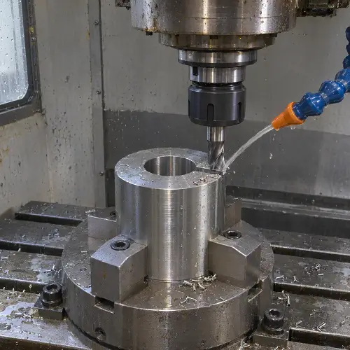
Shaft coupling machining begins with the component drawing and its role in the assembly. A rigid sleeve, a split hub, and a jaw coupling hub may all be cylindrical, but they require different machining and inspection plans.
Preparing the Blank and Machining References
The blank may be bar stock, a forging, a casting, or another suitable starting form, depending on the design and production requirements.
The process establishes reference surfaces that can be used throughout machining and inspection. These often include a bore axis, an end face, or a locating diameter.
Choosing those references matters because the final features need to relate to each other. A bolt pattern positioned correctly relative to the outside surface may still be wrong if the drawing controls it from the shaft bore.
Material condition and any heat treatment should also be planned before finishing critical features. Otherwise, later processing may change dimensions that were already machined to size.
Turning Outside Diameters, Faces, and Bores
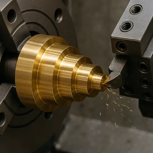
CNC turning produces the main rotational features: outside diameters, end faces, shoulders, recesses, and bores.
Depending on the requirement, a bore may be drilled and then bored, reamed, or otherwise finished. The selected process must achieve the required size, geometry, and surface condition.
Where possible, related features are machined in a setup that helps control their alignment. This is particularly important when both ends of a rigid coupling must share the specified axis.
Outside diameter accuracy alone does not show whether the coupling will fit or rotate correctly. The shaft connection and its relationship to the other functional surfaces are usually more important.
Milling Slots, Jaws, and Fastening Features
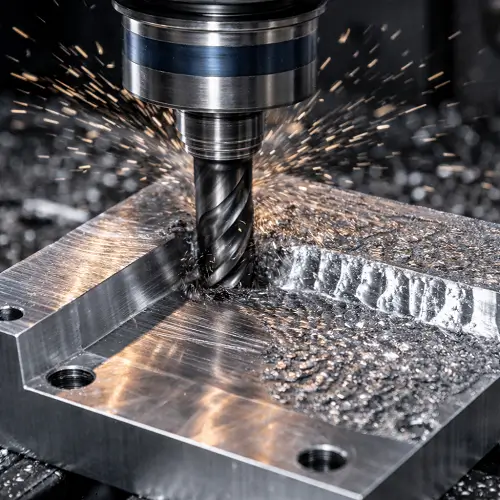
Milling adds clamp slots, split lines, jaw profiles, screw clearances, threaded holes, and mounting features.
For a clamp hub, the slot and screw arrangement determine how the part closes around the shaft. For a jaw hub, the engagement surfaces must match the specified insert.
Tool access affects the available geometry. Internal corners produced by a rotating cutter have a radius, so the design must either allow that radius or specify another manufacturing method.
CNC slot milling also requires attention to slot depth, width, and the material remaining around it. Extending a slot to simplify machining may change the part’s strength or clamping behavior.
Cutting Keyways and Splines
Internal keyways may be produced by broaching, slotting, EDM, or another suitable method. The choice depends on the bore geometry, material, feature length, and whether the bore is open at both ends.
Splines need a process appropriate to the specified tooth form and fit. Tooth count alone is insufficient to define the connection.
Blind features require particular attention to tool access and termination geometry. A drawing should show the required engagement length and any permitted relief rather than leaving the end condition undefined.
Finishing and Inspecting the Part
Deburring removes unwanted material from bore entries, slots, cross holes, and threaded features. It should leave clean assembly edges without rounding away functional geometry.
If a coating or other surface treatment is required, its effect on finished dimensions needs to be included in the process plan. A bore that fits before treatment may no longer fit afterward.
Inspection then checks the specified dimensions and relationships. Where balancing or assembly performance testing is required, those are separate requirements that must be defined for the relevant configuration.
Which Materials Are Used for Machined Shaft Couplings?
Material selection affects mass, stiffness, strength, corrosion resistance, and the machining process. It should follow the component’s function rather than the assumption that one material is best for every coupling.
Aluminum
Aluminum is useful where low mass and rotational inertia are important. It is commonly considered for compact hubs and certain one-piece flexible coupling designs.
It is also readily machinable, but its lower elastic modulus compared with steel matters when stiffness is important. The geometry must provide the required behavior.
Clamp features, threaded holes, and thin flexible sections need appropriate design. A lightweight body still needs enough material to withstand its fastening and operating loads.
Carbon and Alloy Steel
Carbon and alloy steels are used where the specified strength, wear behavior, or section loading makes them suitable.
Some designs require heat treatment. The material grade and condition must therefore be defined clearly, and the machining sequence should allow for possible distortion and any final finishing operations.
For a coupling hub, changing the steel grade without considering its heat-treated condition can change both manufacturability and performance. “Steel” alone is not a complete material specification.
Stainless Steel
Stainless steel can be appropriate where the coupling component is exposed to moisture, cleaning chemicals, or another corrosive environment.
The grade needs to match the mechanical and environmental requirements. A grade selected for easier machining may not provide the same corrosion or strength characteristics as another stainless steel.
For custom parts, specify the grade and condition rather than relying on appearance. A polished surface does not establish corrosion suitability.
Elastomers and Engineering Plastics
Flexible coupling assemblies may contain elastomeric spiders or engineering-plastic center discs.
These are functional components. Their hardness, stiffness, wear behavior, temperature capability, and fluid compatibility influence the assembly.
A drawing package should identify the required element or mating interface. The machining supplier should not have to choose an unspecified insert simply because it fits between the hubs.
What Features Matter Most in Shaft Coupling Machining?
A coupling can look well finished and still assemble poorly. The features that contact the shafts, locate the components, and transmit load deserve the most attention.
Bore Size and Shaft Engagement
The bore must match the shaft and the chosen attachment method.
Too much clearance can affect positioning or clamping. Too little clearance can prevent assembly or encourage damage during installation.
Engagement length also matters. A short hub provides less contact length than a longer one, which can affect the connection’s load capacity.
The coupling and mating shaft machining requirements should be coordinated. Tightening the bore requirement alone will not correct an unsuitable shaft diameter, surface condition, or connection design.
The Relationship Between Bores and Faces
For rigid couplings, the relationship between the shaft bores is central to the function. For flanged parts, the mounting face and locating features may also need controlled runout relative to the bore axis.
The drawing should identify the relevant datum and geometric controls. Specifying each diameter without controlling their relationship can leave an important part of the design undefined.
These controls should reflect how the component locates in the assembly. Applying a tight requirement to an unrelated outside surface adds inspection work without necessarily improving function.
Keyways, Splines, and Axial Retention
Keys and splines transfer torque through their contact surfaces. Their fit, alignment, and usable engagement length need to match the mating shaft.
A key does not automatically prevent the hub from moving along the shaft. Axial retention may still require a shoulder, clamp, retaining feature, or another specified arrangement.
This is why the complete shaft connection matters more than an isolated keyway dimension.
Clamp Slots and Screw Features
A clamp hub needs room to close and grip the shaft. The slot, screw position, wall section, and bore work together.
If the slot closes completely before sufficient grip develops, tightening the screw further does not provide the intended clamping action.
Screw holes also need adequate engagement and access. A hub that can be manufactured but cannot be tightened in the equipment is not ready for production.
Backlash and Torsional Stiffness
Backlash is lost motion caused by clearance before the driven side responds. Torsional deflection is twisting under load.
These are different properties. A zero-backlash coupling can still deform elastically enough to affect positioning.
For a custom design, machining controls the specified geometry, but the complete structure and materials determine the resulting stiffness and load response. A dimensional inspection report alone does not demonstrate every performance characteristic.
What Makes Shaft Couplings Difficult to Machine?
The main difficulties come from features that change shape during processing, surfaces that are difficult to reach, and relationships that must remain accurate across several operations.
Split Hubs Can Change Shape
Cutting a split or clamp slot can release residual stress and change the bore shape. Clamping the part during machining or inspection can also distort it.
The process needs to account for when the split is made, how the part is supported, and whether bore acceptance applies in the free or specified assembled condition.
This avoids a part that passes inspection under one clamping condition but does not fit correctly during use.
Flexible Sections Need Controlled Machining
Beam coupling slots leave thin sections that act as springs. Cutting forces, residual stress, and excessive edge removal can alter those sections.
The machining method must preserve the designed geometry and produce a suitable edge condition. Burr removal should not become uncontrolled rounding or thinning.
The finished part also needs appropriate verification for its intended duty. Accurate slot dimensions are necessary, but they do not independently establish fatigue life.
Internal Features Can Limit Tool Access
Deep keyways, blind splines, and restricted bores may need specialized processes or relief features.
These requirements should be identified during the machining review. Moving or changing a functional feature after the rest of the part has been completed can cause avoidable rework.
Where a small geometry change would improve access, it should be reviewed against the mating component before it is adopted.
Heat Treatment and Finishing Can Affect Fit
Heat treatment may change part geometry, while coatings can change fitted dimensions.
The manufacturing sequence should allow critical features to reach their final requirements after the relevant processes. That may mean leaving machining allowance or specifying areas to be masked during coating.
Without that planning, a component can be correct at an intermediate stage and incorrect when delivered.
When Do You Need Custom Shaft Couplings?
Custom shaft couplings are useful when a standard product cannot meet the required connection geometry, installation space, or component interface.
Common reasons include different bore sizes at the two ends, special keyways or splines, restricted outside dimensions, and nonstandard mounting features.
Custom machining can also produce individual hubs, sleeves, flanges, or spacers for a larger coupling assembly. This can be appropriate when the flexible element is already specified and only the metal interfaces need to change.
At JeekRapid, custom coupling bodies and hubs can be reviewed for machining from customer drawings, with the supplied components and inspection requirements identified before production.
A shaft coupling manufacturer or machining supplier should distinguish between manufacturing a part to an approved drawing and validating a complete coupling design. Changes to bore size, slot geometry, material, or hub length should not automatically inherit the rating of a standard product.
For repeat production, an approved drawing revision provides the reference for machining and inspection. Changes made during prototype evaluation should be incorporated before the next batch is ordered.
Conclusion
Shaft coupling types differ in how they transmit torque, accommodate movement, and connect to the shafts. Those differences determine which features need to be machined and which parts must be supplied as separate assembly components.
Reliable shaft coupling machining depends on more than producing a clean outside surface. Bore fit, feature alignment, keyways, clamp geometry, and finishing requirements all affect whether the part assembles and functions as intended.
JeekRapid provides CNC machining for custom coupling bodies, hubs, sleeves, and flanged components. Send your CAD model and drawing for a machining review and quote to discuss the connection features, quantity, and manufacturing requirements for your project.