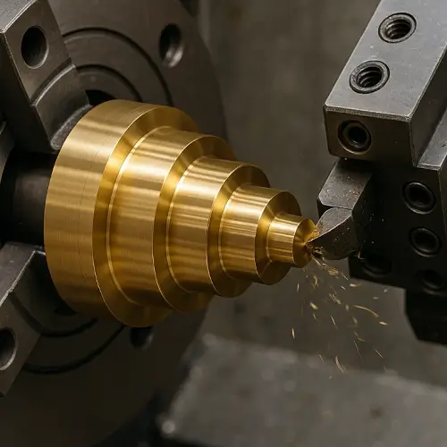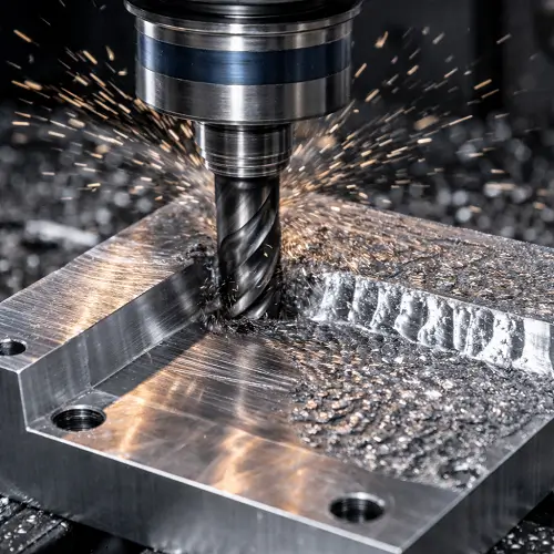
CNC milling parts are used to mount equipment, protect electronics, locate moving components, and connect fluid passages. Their usefulness depends on how well their features work together. A mounting plate needs holes that match the equipment above it. An enclosure needs enough space for its internal components, connectors, and assembly tools.
Choosing the right design starts with the part’s job. This guide explains which parts can be milled, when milling is a practical choice, and what to check before sending a drawing for production.
What Are CNC Milling Parts?
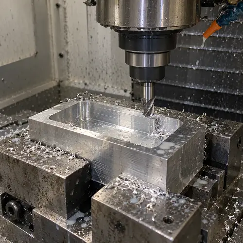
CNC milling parts are components produced by rotating cutting tools that remove material from a workpiece. The machine follows a programmed path to create surfaces, pockets, slots, holes, and contours, often starting from a metal or plastic block.
For example, an aluminum housing may begin as solid stock. Machining removes material from the interior, creates mounting surfaces, and adds connector openings and threaded holes. Several tools and workpiece orientations may be needed to complete the part.
“CNC milling parts” and “CNC milled parts” generally refer to the same finished components. They are different from milling machine components, such as spindles and tool changers, which belong to the equipment itself.
What Parts Can Be Made by CNC Milling?
Housings and Enclosures
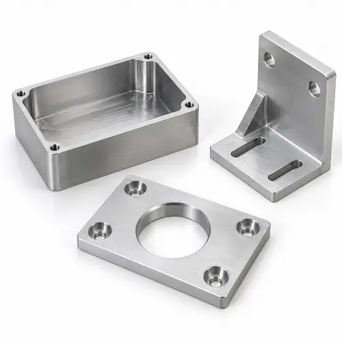
A custom CNC enclosure is useful when a standard box cannot accommodate the required component layout, mounting points, connectors, or sealing arrangement. Milling can incorporate these features into the housing instead of relying on separate brackets and adapters.
For an electronics housing, the internal pocket must clear both the circuit board and the components mounted on it. Rounded pocket corners can interfere with a square board, while mounting posts can contact solder joints if their position or diameter is wrong.
Connector openings also need more than clearance for the connector body. A retaining nut, cable plug, or installation tool may need additional space. Supplying the internal layout and mating lid helps the manufacturer check these relationships before cutting material.
Brackets and Mounting Blocks
Milled brackets support motors, sensors, cameras, and actuators. They are useful when mounting faces need to maintain a defined relationship or when the part combines steps, pockets, and locating features.
Consider a motor bracket for a belt-driven assembly. Slots may allow the motor to move for belt adjustment. Once positioned, the bracket must support the motor without shifting under load. If the motor needs to return to the same position after removal, the design may also need locating pins, a register, or another positive locating feature.
A clearance hole allows a bolt to pass through. It does not, by itself, establish an accurate and repeatable location. The drawing should distinguish between features that fasten the assembly and those that position it.
Mounting Plates and Fixture Plates
Mounting plates connect several components to a shared base. Fixture plates hold and locate workpieces during machining, assembly, or inspection.
A plate supporting two linear rails illustrates why the hole pattern matters. The overall plate dimensions can be correct while the rails are positioned incorrectly relative to each other. The drawing should define the mounting face and the features used to establish rail position.
For fixture plates, identify whether holes receive bolts, locating pins, bushings, or threaded inserts. These features require different preparation. If replaceable components are involved, provide their specifications rather than expecting the manufacturer to infer the required fit from a nominal hole size.
Manifold Blocks
CNC machined manifolds route air, oil, coolant, or other fluids through connected passages. A single block can replace several separate fittings and sections of external tubing.
The drawing needs to show which passages connect and which must remain separate. Port specifications should include the thread standard and sealing arrangement. A fitting may screw into a port without forming the intended seal.
Intersecting passages also need attention. Burrs can remain where drilled holes meet, and drilling access holes may require plugs. Specify cleanliness requirements, plug details, and any leak or pressure testing needed for the finished assembly.
Heat Sinks and Cooling Components
Milled cooling components can combine a contact face, mounting holes, pockets, and fins. This is useful when a standard heat sink cannot fit the available space or accommodate the equipment layout.
The face touching the heat source needs to work with the selected thermal interface material and fastening arrangement. A shiny surface is not proof that the contact face is sufficiently flat. Mounting holes must also place the component correctly without interfering with nearby electronics.
For long, straight fins with a constant cross-section, an extrusion followed by machining may be more practical than milling the entire part from a block. The appropriate heat sink design depends on both the thermal requirements and the production route.
When Is CNC Milling a Good Choice for Custom Parts?
CNC milling is worth considering when a part needs several accurately related features, such as a mounting face, internal pocket, side opening, and locating holes. Producing these features in one component can reduce the number of separate pieces that must be aligned during assembly.
It is also useful for prototypes and smaller production runs where dedicated tooling would be difficult to justify. If a housing design is still changing, its machining program and setup can often be revised without replacing a production mold. Fixtures and programming still require work, so design changes should be reviewed rather than treated as automatically cost-free.
The part’s shape can point toward a different process. A sleeve dominated by concentric outside and inside diameters is usually a candidate for turning. A simple, uniform-thickness bracket may be better made from sheet metal. A long profile with an unchanged cross-section may suit extrusion with secondary machining.
| Part requirement | Process worth evaluating | Reason |
|---|---|---|
| Housing with pockets, mounting posts, and side openings | CNC milling | Several functional features can be machined into one body |
| Round shaft or sleeve with concentric diameters | CNC turning | The geometry suits a rotating workpiece |
| Thin bracket with simple bends and holes | Sheet metal fabrication | It may avoid removing large amounts of solid stock |
| Long cooling profile with straight, repeated fins | Extrusion plus machining | The extrusion forms the repeated profile; machining adds local features |
| Stable design required in large quantities | Casting or molding with secondary machining | Dedicated tooling may become economical at the required volume |
A component can also use more than one process. A casting may need its mounting faces and bores machined afterward. A turned part may require milled flats or side slots. The aim is to choose a production route that delivers the required features reliably.
Where Are CNC Milled Parts Used?
In automation and robotics, milled parts position motors, guide rails, grippers, and sensors. For a sensor bracket, the sensing position and adjustment range may be the main concerns. For a gripper mounting plate, stiffness and alignment under load may matter more. Both are milled parts, but they should not receive identical drawing requirements.
Electronics and optical equipment use housings, mounting frames, and cooling components. Aluminum milled parts are often considered where weight and heat transfer matter. Plastic components can provide electrical isolation, although the selected grade must also suit the temperature, load, and operating environment.
Medical and laboratory equipment use sample holders, instrument brackets, and equipment housings. A bracket inside a dry instrument faces different conditions from a holder exposed to repeated cleaning. Specify the cleaning chemicals and operating conditions when they affect material or finish selection.
Fluid-handling equipment uses manifold blocks and valve components. Stainless steel milled parts may be appropriate for some corrosive environments, while engineering plastics may suit certain chemical or insulation requirements. The exact material grade should follow the fluid, temperature, pressure, and mechanical demands.
How Are Custom CNC Milling Parts Made?
The manufacturer first reviews the model, drawing, and order requirements. The model shows the geometry; the drawing identifies details such as threads, critical dimensions, reference surfaces, and finishing requirements. If these documents disagree, the conflict should be resolved before machining.
The next decision is how to hold the workpiece and reach its features. A plate with pockets on its upper face may need a straightforward setup. A housing with openings on several sides requires additional orientations, suitable fixtures, or multi-axis machining. Five-axis equipment can improve access for certain geometries, but it is not automatically necessary for every complex-looking part.
Rough machining removes most of the unwanted material. Finishing operations establish the required surfaces and dimensions. Holes may be drilled, bored, or reamed, while threads may be tapped or thread milled. The operations are selected according to each feature’s function.
Deburring, surface treatment, and inspection follow the agreed production sequence. When a finish affects assembly, the drawing must establish whether the critical requirement applies before or after finishing.
JeekRapid provides custom CNC milling parts from customer drawings, with machining access, functional features, surface treatment, and inspection requirements reviewed before production.
What Design Features Make a Part Difficult to Mill?
Sharp Internal Corners
An end mill leaves a radius in the internal corners of a pocket. A smaller cutter can reduce the radius, but it cannot create a perfectly sharp internal corner through ordinary end milling.
This can cause trouble when a square component must seat inside the pocket. Increasing the pocket’s overall width may provide clearance, but it can also remove support or weaken the surrounding wall.
Better options may include rounding the mating component’s corners or adding local corner relief where the structure permits it. If the sharp corner is essential, an additional process may be required. Providing the mating component helps the manufacturer evaluate the actual interference.
Deep, Narrow Pockets
Deep, narrow pockets restrict the size and reach of the cutting tool. A long, slender tool is more likely to deflect, and removing chips becomes more difficult. These conditions can leave chatter marks or inconsistent wall geometry.
Check whether the full depth is needed across the entire pocket. If only one component extends farther into the housing, a local recess may provide clearance without making the whole cavity deeper.
A wider opening or larger internal radius can also improve access. Where the assembly allows it, a separate cover may make an otherwise enclosed feature accessible for machining. Such changes must preserve the part’s strength, sealing, and assembly requirements.
Thin Walls and Floors
Thin sections can move during cutting or clamping. A part may measure correctly while held in a fixture and change shape after release.
For a lightweight enclosure, it may be possible to remove material from nonfunctional areas while retaining support around screw holes, locating features, and sealing faces. Ribs or shorter unsupported wall sections can help where the internal layout allows them.
The manufacturer needs to know which surfaces must remain flat or aligned in the free state. Without that information, checking the part while it is restrained may not reveal the problem that appears during assembly.
Inaccessible Slots and Undercuts
A slot shown in CAD still needs a usable path for the cutter and its holder. A wall, overhang, or nearby feature can block access even when the slot itself is wide enough.
In CNC slot milling, the slot’s position and entry path can therefore matter as much as its dimensions. Some features need special tooling; others may be better produced before a separate component is attached.
Explain why the feature exists. If it retains a cover, for example, an accessible groove or removable retaining plate may accomplish the same task. The manufacturer can evaluate alternatives more effectively when the function is clear.
Why Can a CNC Milled Part Meet Its Dimensions but Still Fail to Fit?
A correct hole diameter does not establish that the hole is in the correct location. Similarly, a pocket can have the specified depth while a nearby raised feature prevents the mating component from seating.
The drawing should identify the surfaces and features that position the part in use. These reference features, called datums, provide the basis for controlling related dimensions. For a plate located by pins and mounted against a base, those features are usually more relevant than an unrelated outside edge.
Finishing can also affect fit. An added coating can reduce hole clearance or change a threaded fit. Identify the finished condition required for critical features and agree on any masking or machining allowance before production.
Burrs and edge treatment are another source of assembly problems. A burr around a mounting hole can prevent full contact. Excessive rounding can remove part of a locating shoulder. Edge requirements should distinguish ordinary exposed edges from functional ones.
If a fit is difficult to describe, supply an assembly section or the mating part drawing. Showing where the components touch is more useful than adding a general note saying “high precision.”
How Do You Choose a CNC Milling Parts Manufacturer?
Ask to see parts with features similar to yours. A supplier that regularly makes flat plates may still need to demonstrate how it would handle a thin-walled housing with deep pockets and side openings.
Then discuss the difficult areas on your drawing. A useful answer explains how the part will be held, how the tool will reach a feature, and which dimensions will be inspected. If a supplier recommends a design change, the reason should be specific. Increasing a nonfunctional pocket radius may improve tool access; changing a locating hole could affect the assembly and needs your approval.
For precision CNC milling parts, inspection must address the relationships that matter. Measuring overall length and width does not establish the position of a locating-hole pattern. Confirm how the critical features will be checked and whether dimensional reports are included.
Also compare the delivery scope. One CNC milling parts supplier may quote bare machined components, while another includes finishing, material certificates, thread inspection, and protective packaging. Resolve these differences before comparing the final prices.
What Should You Send When Ordering CNC Milling Parts?
Provide a 3D model and a 2D drawing when available. Identify the material grade, quantity, finish, thread details, critical requirements, and revision to be manufactured. If you need prototypes first and a larger batch later, state both quantities.
Include a short explanation of how the part functions. “This face supports a linear rail” or “this opening must allow the connector nut to be tightened” gives the supplier information that may not be obvious from the model.
Highlight decisions that are still open. If you are unsure whether a wall can be thinner, mark the wall and explain the space or weight restriction. If a corner radius is negotiable, identify the mating component and available clearance.
When ordering repeat batches, refer to the approved drawing revision and acceptance requirements. If anything changes, including the finish or mating component, communicate it before production rather than assuming the earlier manufacturing plan still applies.
Conclusion
CNC milling can bring mounting surfaces, pockets, holes, and other functional features together in a single part. The right design makes those features accessible to machine and suitable for the way the component will be assembled, loaded, cleaned, or serviced.
JeekRapid supports custom metal and plastic parts from prototypes through production. Send your CAD files, drawings, quantity, and finishing requirements for a manufacturability review and quotation. Include the mating components or highlight any uncertain features so we can discuss machining options and potential adjustments before production.