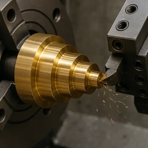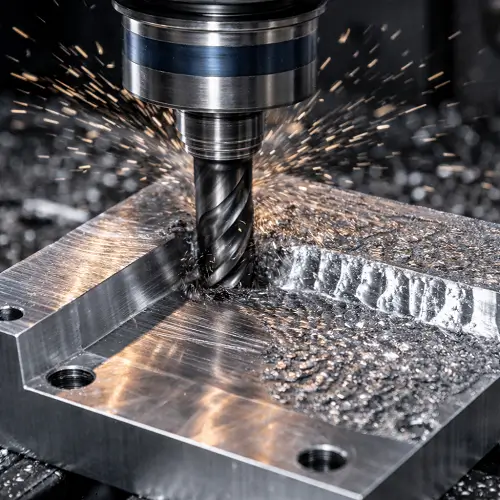
Machined shafts connect motors, bearings, gears, and couplings in equipment that needs controlled motion and reliable power transmission. Their performance depends on more than the outside diameter. Bearing seats establish fit, shoulders locate components, and seal surfaces help prevent leakage. Errors in these areas can cause assembly problems even when the shaft looks correct.
Material selection, machining sequence, and finishing requirements also affect price. Defining the working surfaces and their requirements before production helps avoid paying for unnecessary precision while overlooking the features that actually control performance.
What Is Shaft Machining?
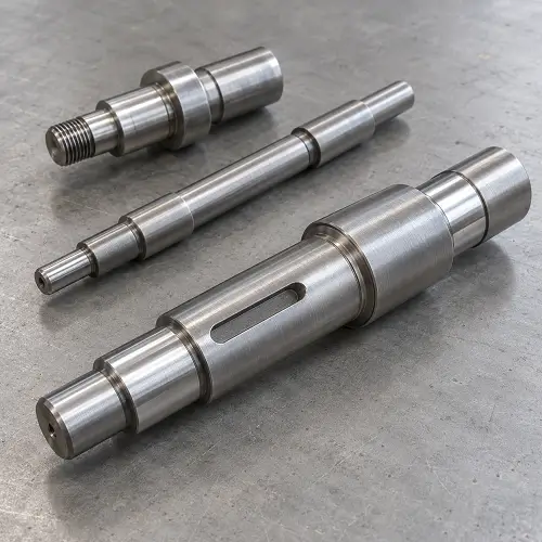
Shaft machining is the process of removing material from stock to create shaft diameters, shoulders, grooves, threads, holes, and torque-transmitting features. Turning produces most round surfaces, while milling, drilling, and grinding add features or finish critical areas. The completed shaft must meet its specified dimensions, geometry, material condition, and surface requirements.
A simple shaft may need only turning and deburring. A stepped shaft with bearing journals, a keyway, and threaded ends requires additional operations. If heat treatment is specified, the machining plan must also account for dimensional movement before critical surfaces reach their final size.
CNC shaft machining supports complex profiles and repeat production, but consistency still depends on workholding, tool condition, and inspection. Running the same program does not eliminate variation caused by tool wear or movement during clamping.
What Types of Shafts Can Be Machined?
Straight and Stepped Shafts
Straight shafts have a largely constant outside diameter, sometimes with end threads, flats, or retaining-ring grooves. They are used in rollers, guides, and assemblies where components attach along a common axis.
Stepped shafts have several diameters to accommodate bearings, gears, spacers, or couplings. Their shoulders establish axial positions, while individual journals provide the required fits.
For stepped shaft machining, the drawing should identify the bearing seats and locating shoulders. A tight outside-diameter tolerance cannot compensate for a shoulder in the wrong position or two journals that do not run correctly relative to the specified datum axis.
Keyed Shafts
A keyed shaft transfers torque through a key fitted between the shaft and a mating hub. The keyseat needs a defined width, depth, length, and position so the key engages both components correctly.
Shaft keyway machining also requires attention to the slot ends. An end-milled keyseat normally has a rounded end, which must clear the key and mating assembly. A slot placed immediately beside a large shoulder may restrict cutter access.
The key size should follow the mechanical design. Enlarging the slot simply to use an available cutter changes the fit and reduces the remaining shaft section.
Splined Shafts
Splined shafts use multiple teeth to engage a matching internal spline. They are used where the connection needs to transmit torque and, in some designs, allow axial movement.
A spline cannot be fully specified by its outside diameter and tooth count. The drawing needs the applicable standard, tooth geometry, fit, engagement length, and inspection requirements. For involute splines, details such as pressure angle and module or diametral pitch are essential.
Suitable tooth-cutting methods may include milling, hobbing, or shaping, with grinding where the specification requires it. The process must be selected for the actual spline rather than treating every toothed shaft as the same machining job.
Hollow and Threaded Shafts
Hollow shafts provide an internal passage or reduce mass. A short bore is a different manufacturing task from a deep bore through a slender shaft. Bore size, straightness, wall thickness, and alignment with the outside surfaces can all affect the process.
Threaded shafts may use end threads to retain a nut, bearing, or coupling. Specify the thread size, pitch, class, and usable thread length. If a nut must seat against a shoulder, provide enough clearance for the incomplete threads at the termination so they do not prevent seating.
What Matters When Machining Motor, Pump, and Drive Shafts?
These names describe the application. A motor shaft can also be stepped and keyed, while a pump shaft can include threads, bearing seats, and seal surfaces. Understanding the application helps identify which features need the most attention.
Motor Shafts
Motor shafts connect the rotor to the driven equipment. The relationship between the bearing journals, rotor seat, and coupling seat affects how the assembly runs.
The drawing should identify the datum arrangement, journal fits, rotor mounting dimensions, and shoulder positions. If balancing is required, the specification should state the balancing condition, including whether the shaft is checked alone or as part of a rotor assembly and how keys are treated. Dimensional inspection and balancing verify different requirements.
Pump Shafts
Pump shaft machining requires information about both the mechanical assembly and the operating environment. The supplier needs to know the material specification and whether the shaft contacts the pumped fluid, cleaning chemicals, or only an isolated bearing area.
The seal arrangement matters. A radial lip seal may run directly on the shaft or a sleeve, while a mechanical seal has its own mounting and locating requirements. Identify the actual working surfaces instead of applying one finish to the entire shaft.
The impeller attachment also needs clear dimensions. Threads, keys, tapers, and shoulders must locate the impeller as intended without interfering with the seal or bearing positions.
Drive Shafts
Drive shafts transmit torque through components such as gears, pulleys, and couplings. Their material condition and geometry need to suit the applied loads, including repeated loading and shock where relevant.
For manufacturing, the important information includes the coupling interfaces, keyways or splines, bearing locations, and required hardness. If the drawing is still being developed, operating speed, torque, and bearing spacing help identify questions that need engineering resolution before production.
A machining supplier can review manufacturability, but cutting an existing shape accurately does not establish that its mechanical design is suitable for the intended load.
Which Material Is Best for a Machined Shaft?
The starting point is the shaft’s environment and function. A dry indoor adjustment shaft, a heavily loaded drive shaft, and a pump shaft exposed to process fluid need different combinations of properties.
1045 Carbon Steel
1045 is a practical candidate for general machinery shafts that need more strength than mild steel while keeping material and processing costs reasonable. It can also be surface hardened when wear resistance is required.
Its main limitation is corrosion. Shafts exposed to moisture may need protection, lubrication, or another material. The drawing should identify the required material condition and any hardness requirement; “1045” alone does not define the finished properties.
4140 Alloy Steel
4140 is worth evaluating when the design requires higher strength, toughness, or fatigue performance than the proposed carbon-steel condition provides. Those benefits depend on the specified heat treatment.
Prehardened 4140 and annealed 4140 followed by hardening lead to different manufacturing routes. The quote should identify which condition is being supplied and whether final grinding or other finishing is included.
Changing from 1045 to a stronger steel does not, by itself, solve excessive elastic bending. If deflection is the problem, shaft diameter, unsupported span, and bearing arrangement also need review.
Stainless Steel
303 stainless steel is useful for shafts with multiple turned or threaded features when the environment is mild and machinability is important. Its improved machining behavior comes with reduced corrosion resistance compared with 304 and 316.
For wet environments or repeated cleaning, evaluate 304 and 316 stainless steel against the actual exposure. 316 offers improved resistance to chloride attack, but it should not be treated as suitable for every chemical or seawater condition.
17-4 PH is another candidate when both higher strength and corrosion resistance matter. Specify the heat-treatment condition so machining, final properties, and inspection are based on the same requirement.
Stainless steel shaft machining may also include passivation when required to remove free-iron contamination after processing. Passivation does not turn an unsuitable alloy into a suitable one for the application.
Aluminum
Aluminum shafts can reduce mass in mechanisms with modest loads. However, an aluminum shaft generally deflects more than a steel shaft of the same geometry under the same load.
Wear at bearing, bushing, and sliding-contact areas also needs evaluation. Aluminum is a useful option when the complete design benefits from its low weight, rather than simply because it is fast to machine.
| Main requirement | Material to evaluate first | What must be confirmed |
|---|---|---|
| General machinery shaft with manageable corrosion exposure | 1045 | Required strength, material condition, and protection against rust |
| Higher-load drive shaft | Heat-treated 4140 | Required hardness, section properties, and fatigue requirements |
| Complex machining in a mild environment | 303 stainless steel | Whether its corrosion resistance is sufficient |
| General wet service or cleaning exposure | 304 stainless steel | Fluid chemistry, temperature, and cleaning conditions |
| Greater chloride resistance | 316 stainless steel | Suitability for the actual exposure, not just the industry name |
| Higher strength with corrosion resistance | 17-4 PH | Heat-treatment condition and environmental compatibility |
| Low mass in a lightly loaded mechanism | Aluminum alloy | Deflection, wear, and contact-surface requirements |
These are starting points for evaluation, not permission to substitute a material already specified on an approved drawing.
What Is the Shaft Manufacturing Process?
The shaft manufacturing process starts with drawing review, material verification, and selection of the machining sequence. Critical surfaces, treatment requirements, and inspection methods should be identified before stock is cut.
Many custom machined shafts start from bar stock. Forged blanks may be suitable for other shapes or production requirements, but a separate forging operation is not necessary for every shaft.
Turning the Diameters and Shoulders
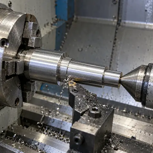
The stock is faced and held in a chuck, collet, or suitable between-centers arrangement. Rough turning removes the bulk of the material, followed by passes that establish the diameters and shoulder positions.
Related journals are machined in a common setup where practical. When the shaft must be repositioned, the second setup needs a controlled reference so features machined from opposite ends retain the required relationship.
On shafts that will be hardened later, selected surfaces may remain oversize for final machining after treatment.
Adding Keyways, Holes, Grooves, and Threads
Milling adds features such as flats and keyways. Drilling creates axial or cross holes, while turning and thread-cutting operations produce grooves and threaded sections.
The sequence should preserve useful clamping surfaces and protect completed journals. A finished bearing seat should not acquire chuck damage during a later operation.
Burrs around cross holes, keyways, and threads also need controlled removal. An edge that passes through a seal or bearing during assembly should not be left sharp or damaged, but deburring must not remove material needed for the specified fit.
Heat Treatment and Final Finishing
When hardening follows rough machining, dimensional movement may require subsequent finishing. Stock allowance should be planned around the material, treatment, geometry, and final process.
Some shafts can be machined from prehardened stock without a later hardening stage. Others require through-hardening, localized surface hardening, or aging to achieve the specified condition.
Final inspection should apply to the delivery condition. If a coating affects a fitted diameter, checking only the uncoated shaft does not establish that the finished part will assemble correctly.
What Tolerances and Surface Finish Does a Shaft Need?
There is no single shaft tolerance that suits every journal, material, and assembly. Assign requirements according to what each surface does.
Bearing-Seat Diameter and Fit
Start with the selected bearing and its operating arrangement. The bearing type, size, load, temperature, and mounting requirements influence the required shaft limits.
Once the appropriate bearing fit tolerance is established, put the finished diameter limits or fully defined fit specification on the drawing. A note such as “bearing seat” or “tight fit” leaves too much unresolved.
The shaft limits must be considered together with the bearing bore limits. Making a shaft slightly larger than the nominal bearing size does not establish a controlled interference fit.
Tolerance notation also needs careful reading. A diameter specified at ±0.0005 in permits a total variation of 0.0010 in. That is different from a total tolerance zone of 0.0005 in. These numbers illustrate notation only; they are not recommended bearing-seat tolerances.
Runout, Form, and Axial Location
A journal can meet its diameter limits while being misaligned with another journal. Diameter measurement alone does not check that relationship.
Runout requirements need a defined datum axis and clearly identified controlled surfaces. Roundness, cylindricity, and straightness describe other aspects of geometry and should not be used interchangeably.
Shoulder positions establish the assembled locations of bearings, gears, and spacers. Dimension the functional distances deliberately so a stack of individually acceptable lengths does not produce an unacceptable overall position.
Surface Finish
Specify surface roughness on the working surfaces. “Smooth finish” does not tell a manufacturer what to produce or an inspector what to accept.
A bearing seat and a radial seal track can require different surface conditions. For the seal track, the seal supplier’s texture and machining-direction requirements matter; a shiny appearance alone does not establish suitability.
Coated shafts also need a clear final-size requirement. Identify which surfaces receive coating, which are masked, and whether any subsequent finishing is required.
When Is Shaft Grinding Necessary?
Shaft grinding is useful when the proposed turning process cannot reliably achieve the required combination of size, form, surface texture, and material condition. It is often considered for hardened journals and demanding bearing or seal surfaces.
Grinding is not automatically necessary for every bearing seat. If finish turning consistently meets all specified requirements, an additional grinding operation may add cost without improving function.
For a shaft hardened after rough machining, grinding may provide the final sizing operation. The supplier must allow sufficient material and evaluate distortion before finishing. Grinding removes material; it cannot correct unlimited bending while preserving every diameter and wall thickness.
Ask whether grinding is included in the quotation and which surfaces will be ground. “Precision shaft” is too broad to establish the process or the acceptance limits.
Why Are Long, Slender Shafts Harder to Machine?
Long shaft machining becomes difficult when the workpiece bends under cutting forces. A section can move away from the tool during cutting and spring back afterward, leaving excess material or an uneven diameter.
The unsupported length is important. Overall length-to-diameter ratio gives an initial indication of slenderness, but local thin sections, clamping, and intermediate support affect actual behavior.
Tailstock support, steady rests, or follow rests can reduce movement. Tool selection and cutting conditions also need to limit forces while maintaining a clean cut. Simply reducing the feed until the tool rubs is not a reliable solution.
Before quoting, identify whether center holes are permitted and which surfaces must remain free of support or clamping marks. Preventing access to both ends and all outside surfaces can make workholding substantially more difficult.
The inspection setup must also suit the specified requirement. A shaft held straight by excessive fixture force may behave differently when released.
How Can Shaft Design Reduce Machining Cost?
Useful design changes reduce machining difficulty while preserving function.
At a shoulder, the fillet radius must clear the mating component. A radius that improves the shaft’s transition can still prevent a bearing or hub from seating if the mating chamfer is too small. Define the interface rather than asking for an unspecified “small radius.”
Use established key, thread, and retaining-ring sizes when they suit the assembly. Unusual groove widths or features placed close to a large shoulder may require special tooling or additional operations.
Deep axial holes deserve particular review. Clarify whether the bore is a precision locating surface or only a passage. Applying tight size and alignment requirements to a noncritical passage can add processing and inspection work without improving its purpose.
Concentrate tight tolerances on functional areas. A noncontact section between two bearing journals usually does not need the same diameter control or finish as the journals unless another requirement justifies it.
Any change to an approved feature must be agreed before manufacture. A cheaper quote based on silently relaxing the drawing is not a lower price for the same part.
How Are Precision Shafts Inspected?
Inspection should verify the features that control assembly and operation. One outside-diameter reading and a visual check are insufficient for a shaft with several fitted surfaces.
Journals should be measured at appropriate positions along their length and around their circumference. These checks help identify dimensional variation, but acceptable micrometer readings alone do not prove full roundness or cylindricity compliance.
| Drawing requirement | Appropriate verification |
|---|---|
| Journal diameter | Calibrated micrometer or suitable dimensional gauge |
| Runout to a datum axis | Indicator or measuring system using the specified datum arrangement |
| Roundness or cylindricity | Form-measuring equipment or another validated method with adequate capability |
| Shoulder position and feature relationships | Suitable dimensional equipment, including CMM where appropriate |
| Surface roughness | Profilometer on the specified working surface |
| Threads | Appropriate gauges and checks of usable thread length |
| Spline fit and tooth geometry | Suitable spline gauges or analytical measurement as required |
| Material and heat-treatment condition | Material records, treatment documentation, and specified hardness testing |
Inspection capability must match the tolerance. A CMM is useful for many dimensional relationships, but its presence does not establish that surface texture or every form requirement has been verified.
For repeat orders, the drawing revision, material condition, and inspection requirements should remain consistent with the approved part. Include requested reports and traceability in the quotation scope.
What Affects Shaft Machining Cost?
Shaft machining cost includes material, programming, setup, cutting, treatment, finishing, and inspection. Overall length and diameter alone cannot establish a useful price.
A large starting diameter with much smaller finished sections increases material removal. Slender geometry may require additional support, while keyways, cross holes, and features on several orientations add operations. Harder material conditions and demanding finishes can increase machining time and tool consumption.
Heat treatment, grinding, and coatings introduce separate processing stages. Minimum batch charges can make these operations particularly significant for small orders.
Quantity changes how programming and setup costs are distributed. Request prices for the actual prototype quantity and the expected production quantity rather than assuming the prototype unit price will apply to every order.
When comparing CNC machining cost, confirm that each quotation includes the same finished requirements. A turned shaft without treatment or final grinding is a different deliverable from a hardened, ground, inspected shaft.
Delivery requirements should also cover the complete process. CNC machining lead time must account for material procurement, secondary processing, and final inspection—not only time on the lathe.
What Is Needed to Order a Custom Machined Shaft?
For custom shaft machining, provide a 3D model and a dimensioned drawing whenever possible. The model communicates geometry, while the drawing establishes fits, datums, threads, surface requirements, and material condition.
Include quantity, required delivery date, and documentation requirements. Identify the bearing, seal, hub, or coupling when an interface still needs clarification. This allows unresolved fit requirements to be discussed before the quotation becomes a production order.
Spline specifications should include the applicable standard and fit details. Heat-treatment notes should define the final condition or hardness and any localized requirements. Coating notes should identify thickness, masking boundaries, and finished dimensions.
A sample can support custom shaft manufacturing, but wear makes reverse engineering less straightforward. A worn journal or damaged thread may no longer represent the intended size. Confirm those features using mating components or original documentation before approving the replacement drawing.
Get a Quote for Your Shaft Machining Project
A shaft quotation should cover the finished part that will enter the assembly: the correct material condition, defined bearing and seal surfaces, required treatments, and agreed inspection. Resolving these details before production reduces the risk of paying for parts that need additional work before they can be used.
JeekRapid provides CNC machining services for custom shafts and other precision components, from prototypes to repeat production. Send your CAD model, 2D drawing, quantity, and target delivery date for a manufacturability review and project-specific quotation. Our team can review turning and milling requirements, critical fits, finishing needs, and inspection expectations before production begins.
If material choice, grinding requirements, or a costly tolerance is still undecided, highlight it in the request. We can discuss practical manufacturing options for approval and quote prototype and production quantities separately, helping you compare the cost of the complete part before placing an order.