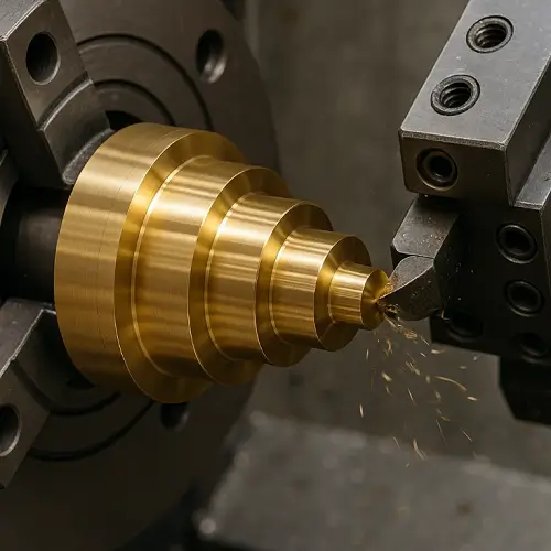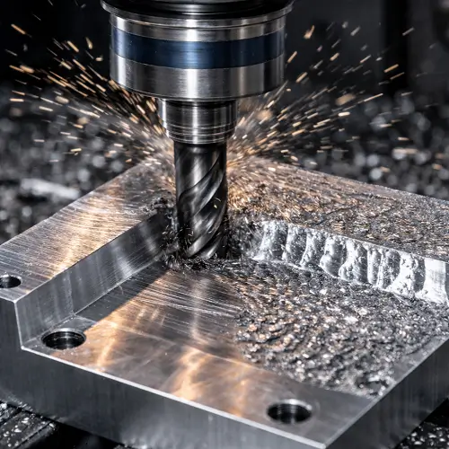
A CNC machined part can meet every dimensional tolerance and still fail during assembly. A small burr around a drilled hole may stop two surfaces from seating correctly. A loose burr inside a hydraulic manifold can break away and block a valve. On parts handled by operators, an untreated edge can also become a safety risk.
This is why deburring should not be treated as a purely cosmetic finishing step. It is a controlled manufacturing operation that affects assembly, cleanliness, sealing, fatigue performance, and part reliability.
This guide explains what deburring is, why burrs form, the main deburring methods and tools, and how engineers should specify edge requirements on CNC machined parts.
What Is Deburring?
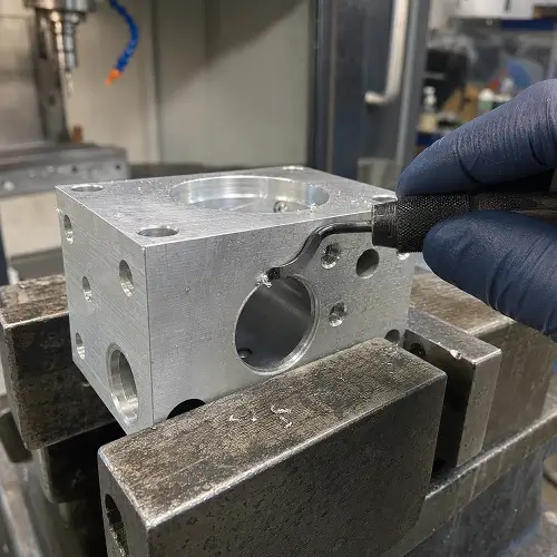
Deburring is the process of removing unwanted raised material, sharp projections, and loose fragments left on a part after machining, cutting, forming, or casting.
These unwanted projections are called burrs. They commonly appear where a cutting tool enters or exits the workpiece, around drilled holes, along milled edges, at thread openings, and where two internal passages intersect.
Deburring removes this unwanted material without changing the intended geometry of the part. A properly deburred edge should be clean, consistent, and suitable for its intended function.
However, deburring does not always mean producing a large chamfer or rounded edge.
The deburring process may be performed manually, with CNC tools, or through mechanical, abrasive, thermal, or electrochemical finishing, depending on the part geometry and production volume.
| Operation | Main purpose | Expected result |
|---|---|---|
| Deburring | Remove unintended material | A clean edge without loose or raised material |
| Edge breaking | Remove edge sharpness | A small radius or chamfer |
| Chamfering | Produce a defined angled surface | A controlled dimension such as 0.2 × 45° |
| Edge rounding | Produce a defined radius | A controlled edge such as R0.3 |
This distinction matters when preparing an engineering drawing. “Deburr” tells the manufacturer to remove unwanted material, while a chamfer or radius callout defines the final edge geometry.
What Causes Burrs in Machining?
A cutting tool does not always separate material cleanly. Near the edge of a workpiece, the remaining material may no longer have enough support to resist the cutting force. Instead of being cut away, it bends, stretches, tears, or fractures.
The result is a burr.
Burr formation is influenced by several factors:
- Workpiece material and ductility
- Cutting tool sharpness
- Tool geometry and coating
- Cutting direction
- Feed rate and depth of cut
- Tool wear
- Workpiece support
- Tool entry and exit position
- Heat generated during machining
Ductile materials such as aluminum, copper, austenitic stainless steel, and some engineering plastics are particularly likely to form rollover or string-like burrs. Harder or more brittle materials may produce smaller but more irregular breakout burrs.
Burrs Produced by Milling
Milling commonly leaves burrs along the top and bottom of an edge. The largest burr often appears where the cutter exits the material because the final section of metal bends outward before it separates.
Tool path direction also affects the location and size of the burr. A process engineer may adjust the milling direction so that the larger burr forms on an accessible, non-critical edge.
Burrs Produced by Drilling
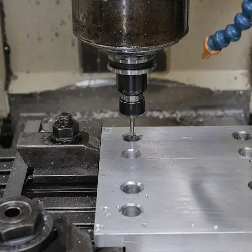
A drill usually creates a smaller burr at the hole entrance and a larger burr at the exit. As the drill tip reaches the opposite surface, the remaining material becomes thin and unsupported. It may deform or fracture before the drill completes the cut.
The problem becomes more difficult in cross holes. The intersection may be deep inside the part, making manual removal and visual inspection difficult.
Burrs Produced by Turning
Turning can leave burrs on shoulders, grooves, thread starts, end faces, and parting-off locations. Dull inserts, unsuitable feeds, built-up edge, and unstable cut-off operations can produce heavy or folded burrs.
Burrs Produced by Tapping and Reaming
Tapping may create burrs around thread entry and exit edges. These burrs can interfere with fastener engagement or break loose during assembly.
Reaming improves hole diameter, roundness, and surface quality, but it does not automatically remove burrs from the back of a hole or from an intersecting passage. These areas may still require a separate deburring operation.
What Types of Burrs Occur on Machined Parts?
Different cutting conditions create different burr shapes. Recognizing the burr type helps manufacturers choose an effective removal method.
Rollover Burr
A rollover burr forms when the cutting tool pushes material over the edge instead of cutting it away cleanly. It is one of the most common burrs found after milling, turning, and drilling.
Rollover burrs are often thin but firmly attached to the workpiece. Ductile metals are particularly susceptible to this type.
Breakout Burr
A breakout burr forms when material fractures as a drill or cutting tool exits the opposite side of the workpiece. The resulting edge may be irregular, chipped, or locally enlarged.
Breakout burrs are common around through-holes and when machining relatively brittle materials.
Poisson Burr
A Poisson burr is created when cutting pressure causes material to deform sideways. It often appears as a raised lip along the side of a machined edge.
This type of burr is associated with plastic deformation rather than direct material tearing.
Tear Burr
A tear burr forms when material is pulled from the surface instead of being sheared cleanly. Dull tools, unstable cutting, built-up edge, and unsuitable cutting parameters can increase tear burr formation.
The affected edge may appear rough and uneven rather than having one continuous folded lip.
Why Is Deburring Important?
A burr may be small, but its effect is not always small. Whether it is acceptable depends on where it is located and how the part functions.
Assembly and Dimensional Accuracy
A raised burr can prevent mating surfaces from sitting flush. It may also interfere with a press fit, bearing seat, threaded connection, alignment pin, or gasket.
The measured part dimensions may be correct, but the assembly can still fail because the burr acts as an unintended spacer.
Sealing Performance
Burrs around O-ring grooves, ports, valve seats, and gasket faces can damage seals or create leakage paths. On hydraulic and pneumatic parts, internal burrs may also detach and travel through the system.
For these parts, removing loose material is just as important as controlling the final edge shape.
Fatigue and Wear
A rough or torn edge creates a local stress concentration. Under repeated loading, vibration, or pressure cycling, this area can become a starting point for fatigue cracking.
Burrs can also contact moving components, increasing friction, wear, and particle generation.
Coating and Surface Treatment
Sharp projections may receive uneven anodizing, plating, paint, or powder coating. Heavy edge rounding can create a different problem by changing the intended geometry before finishing.
Deburring must therefore be coordinated with the final surface treatment rather than performed as an uncontrolled manual step.
Handling Safety
Exposed sheet metal and machined edges can cut operators, assembly workers, or end users. Parts that will be handled regularly often require a defined edge break rather than simple visual burr removal.
What Is a Deburring Tool?
A deburring tool is used to remove raised material, sharp projections, or loose fragments from the edge of a manufactured part. Some tools simply remove an irregular burr, while others produce a controlled chamfer or edge break.
The correct tool depends on where the burr is located, whether the edge is accessible, the workpiece material, and how closely the final edge size must be controlled.
| Deburring tool | Typical application |
|---|---|
| Hand deburring blade | Prototypes and accessible irregular edges |
| Chamfer mill or countersink | Hole entrances and defined external chamfers |
| Back-chamfer tool | Hole exits and rear edges |
| Cross-hole deburring tool | Intersecting internal passages |
| Abrasive brush | Light burrs on exposed surfaces |
| Rotary file or abrasive stone | Heavy localized burrs and manual rework |
A manual blade may be sufficient for a prototype, but it is difficult to control consistently in production. The operator must control the contact angle, pressure, cutting direction, and number of passes.
CNC deburring tools are more suitable when the edge break, cycle time, and part-to-part consistency must be controlled. A programmed chamfer mill can produce repeatable external edges, while back-chamfer and cross-hole tools can reach areas that a standard front-cutting tool cannot access.
Tool selection must also consider material behavior. A blade that cuts aluminum cleanly may rub or wear quickly on hardened steel. An abrasive brush that removes a light burr from stainless steel may round a small aluminum feature if the same pressure and processing time are used.
What Are the Main Deburring Methods?
There is no single deburring method that works for every part. The correct process depends on burr size, part material, edge location, required edge geometry, production volume, and acceptable dimensional change.
| Deburring method | Suitable applications | Main advantage | Main limitation |
|---|---|---|---|
| Manual deburring | Prototypes and accessible edges | Flexible and inexpensive to start | Operator-dependent |
| CNC deburring | Defined external edges and accessible holes | Repeatable and controllable | Requires tool access |
| Brushing or belt deburring | Flat parts and external edges | Fast for exposed surfaces | May round nearby edges |
| Vibratory finishing | Batches of small, robust parts | Processes many parts together | Limited control over individual edges |
| Abrasive flow machining | Internal passages and complex channels | Reaches inaccessible areas | Higher cost and process complexity |
| High-pressure water deburring | Hydraulic passages and internal holes | Removes burrs and loose chips | May not remove heavy attached burrs |
| Thermal deburring | Multiple small internal burrs | Treats many difficult edges at once | Does not create a precise chamfer |
| Electrochemical deburring | Hard, conductive metals and internal features | No mechanical cutting force | Requires dedicated tooling and control |
Manual Deburring
Manual deburring uses files, scrapers, rotary tools, abrasive paper, countersinks, and brushes. It is practical for prototypes, repair work, low-volume production, and complex parts where only a few edges require attention.
Its main limitation is repeatability. Two operators may apply different pressure, angles, and processing times. Excessive manual work can enlarge a hole, round a datum edge, scratch a cosmetic surface, or change a small chamfer.
Manual deburring should therefore have a defined acceptance requirement, especially on precision parts.
CNC Deburring
CNC deburring uses programmed tools inside the machining center. Common tools include chamfer mills, countersinks, back-chamfer tools, rotary brushes, and specialized cross-hole cutters.
This approach can produce a repeatable edge break and reduce separate manual operations. It is particularly effective when the edge is accessible and its location is accurately defined in the CNC program.
CNC deburring is often the most suitable option for production parts requiring controlled edge geometry. However, rigid tools may struggle with cast surfaces, part-to-part variation, curved intersections, and deeply located cross holes.
A supplier providing CNC machining services should review deburring together with the main machining sequence. Completing accessible edge treatment before the part leaves the machine can reduce handling and improve consistency.
Brushing and Abrasive Belt Deburring
Rotary brushes and abrasive belts are efficient for flat surfaces, cut plates, external profiles, and accessible machined edges. They can remove light burrs while improving the visual consistency of the surface.
The process must be controlled around precision features. Excessive contact pressure or processing time can round corners, change small dimensions, or leave an uneven appearance.
Vibratory and Tumbling Deburring
Vibratory finishing places parts in a bowl or tub with abrasive media and a processing compound. Movement between the parts and media gradually removes light burrs and softens exposed edges.
It is economical for batches of small parts, especially when all external edges can receive a similar treatment.
The process is less suitable when one edge must remain sharp, when delicate parts can collide, or when internal passages cannot be reached by the media. It can also change the appearance and texture of the entire exposed surface.
Abrasive Flow Machining
Abrasive flow machining pushes a controlled abrasive-filled medium through or across the part. The medium follows internal passages and removes material from high-resistance areas, including difficult intersections.
This method can reach internal channels that conventional cutters cannot access. It may be considered for manifolds, dies, aerospace components, and parts containing curved or intersecting passages.
Process control is important because material removal may not be uniform throughout a complex flow path.
High-Pressure Water Deburring
High-pressure water deburring directs controlled water jets at holes, internal passages, and edge intersections. It can remove small burrs, loose chips, and contamination while cleaning the part.
It is useful for hydraulic and automotive components that require clean internal passages. Heavy, strongly attached burrs may need to be weakened or reduced during machining before water deburring can remove them reliably.
Thermal Deburring
Thermal energy deburring exposes the part to a short, controlled combustion cycle. Thin burrs have a much higher surface-area-to-volume ratio than the main part, so they heat and oxidize rapidly.
This process can reach many external and internal burrs at the same time. It may be useful for components containing numerous small passages or intersections.
Thermal deburring is not a substitute for a controlled chamfer. Material compatibility, trapped volumes, part cleanliness, oxide residue, and the required edge condition must all be evaluated before selecting it.
Electrochemical Deburring
Electrochemical deburring removes burrs through controlled anodic dissolution. The process targets a selected area without mechanical cutting force or conventional tool wear.
It can be effective on hardened steel, difficult-to-machine alloys, and inaccessible internal edges. Because it works only on electrically conductive materials, it is not suitable for plastics or ceramics.
Electrolyte flow, electrode position, electrical parameters, and masking must be controlled to prevent removal from nearby functional surfaces.
The inclusion of a deburring method in this guide does not mean that every process is completed in-house. Depending on the part geometry and project requirements, specialized secondary processing may be evaluated during the manufacturing review.
Which Deburring Method Should You Choose?
The most economical process is not always the method with the lowest hourly cost. It is the method that produces an acceptable edge repeatedly without damaging the part.
| Part condition | Suitable starting method | Main control point |
|---|---|---|
| One-off prototype with accessible edges | Manual or CNC deburring | Prevent excessive edge removal |
| Defined external chamfer | CNC chamfer milling | Chamfer size and tool wear |
| Large batch of small parts | Vibratory finishing | Media access and part collision |
| Deep intersecting holes | Cross-hole tool, abrasive flow, water or electrochemical method | Complete internal burr removal |
| Multiple small burrs in an enclosed metal part | Thermal deburring | Material and geometry compatibility |
| Hardened conductive component | Electrochemical deburring | Localized material removal |
| Flat laser-cut or machined plate | Belt or brush deburring | Flatness and corner rounding |
| Soft plastic component | Sharp cutting, controlled scraping, or low-speed brushing | low-speed brushingAvoid melting and fuzzy edges |
A practical selection process begins with four questions:
- Where is the burr located?
- How much material must be removed?
- Does the final edge need a defined chamfer or radius?
- How will the result be inspected?
If a burr cannot be reached or inspected, the manufacturing risk increases. This should be considered during both part design and supplier quotation.
For production parts, consistency is often more important than the appearance of one sample. A manual process may produce an acceptable first part but still create excessive variation across hundreds of components. In these cases, CNC, mass-finishing, or specialized automated methods may provide better control.
How Do Different Materials Affect Deburring?
Material behavior strongly affects burr size and removal difficulty.
Aluminum
Aluminum is ductile and can produce long rollover burrs, especially when tools become dull or when a cutter exits an unsupported edge.
Sharp tools, positive cutting geometry, stable tool paths, and planned exit locations help reduce burr formation. Aggressive brushing or tumbling may change cosmetic surfaces, so visible aluminum parts require additional control.
Stainless Steel
Austenitic grades such as 304 and 316 are ductile and prone to work hardening. Rubbing from a dull tool can produce thick, tough burrs that are difficult to remove consistently.
Deburring tools must remain sharp, and the process should avoid excessive heat. For internal features, mechanical, abrasive-flow, or electrochemical methods may be considered depending on the geometry.
Carbon and Alloy Steel
The deburring behavior of steel depends on hardness, microstructure, and heat-treatment condition. Annealed steel may form larger ductile burrs, while hardened steel can produce smaller but more resistant edge defects.
CNC cutting, brushing, vibratory finishing, thermal methods, and electrochemical processes may all be considered, but the final selection depends on the part geometry and edge requirement.
Brass and Copper
Free-machining brass generally produces short chips and relatively manageable burrs. Copper is much more ductile and may smear or fold over an edge.
A method that works well on brass should not automatically be applied to copper using the same parameters.
Titanium
Titanium produces strong, tenacious burrs and retains heat close to the cutting zone. Excessive abrasive contact can generate local heating and affect edge quality.
Sharp tools, stable cutting conditions, and carefully controlled CNC or manual deburring are generally preferred.
Engineering Plastics
POM, nylon, PEEK, and other engineering plastics may produce thin, flexible, or fuzzy burrs. Excessive rotary-tool speed can melt the edge instead of cutting it.
Sharp cutting tools, controlled scraping, low-heat mechanical finishing, or cryogenic deflashing may be used depending on the material and production volume.
How Should Deburring Be Specified on an Engineering Drawing?
“Remove all burrs” and “break all sharp edges” are common drawing notes, but they can be interpreted differently by different suppliers.
One operator may remove only visibly loose material. Another may produce a 0.5 mm chamfer on every edge. Both may believe the drawing note has been satisfied.
A better drawing identifies the edges that affect function and defines an acceptable condition.
Use a Defined Chamfer When Geometry Matters
If the final edge must have a specific shape, state it directly:
0.2 × 45°0.3 × 45°R0.2
These callouts are more appropriate than a general deburring note when the edge controls assembly, flow, sealing, handling, or tool entry.
Identify Critical Edges Separately
Critical edges may include:
- O-ring groove entrances
- Bearing seats
- Press-fit holes
- Valve metering edges
- Thread starts
- Electrical contact edges
- Cross-hole intersections
- Sealing faces
- Measurement datums
Some of these edges must be rounded. Others must remain functionally sharp and only have loose burrs removed. One general note cannot describe both requirements safely.
Use ISO Edge Standards When Appropriate
ISO 13715:2017 specifies drawing rules for edges whose final shapes are not geometrically defined. The standard remains current following its confirmation in 2024.
When a geometrically defined edge such as 1 × 45° is required, it should be dimensioned directly rather than treated as an undefined edge.
Example Drawing Notes
The following are practical examples rather than universal deburring standards:
REMOVE BURRS AND LOOSE MATERIAL. BREAK NON-FUNCTIONAL SHARP EDGES 0.1–0.3 mm.
CROSS-HOLE INTERSECTIONS SHALL BE FREE OF LOOSE BURRS. DO NOT BLEND OR ROUND THE METERING EDGE.
DEBURR HOLE ENTRANCE AND EXIT. MAXIMUM EDGE BREAK 0.15 mm.
The acceptable edge size must be selected according to the part size and function. A 0.3 mm edge break may be reasonable on a large housing but excessive on a miniature precision component.
Drawing requirements always take precedence over general shop practices.
How Can Burrs Be Reduced During CNC Machining?
The most efficient deburring operation is often the one that does not have to remove a heavy burr. Process planning can reduce burr size before the finishing stage begins.
Keep Cutting Tools Sharp
Worn tools push and smear material instead of shearing it cleanly. Tool life should be controlled before burr size becomes unstable.
A tool may continue to produce dimensions within tolerance while already creating unacceptable edge conditions. Burr size should therefore be considered as part of tool-life monitoring.
Control the Tool Exit
Large burrs often form where the cutter or drill exits the workpiece. Changing the tool path, cutting direction, or exit location can move the burr away from a critical edge.
When possible, the tool should exit toward an accessible, non-functional surface.
Support the Exit Surface
Backing material or an adjusted machining sequence can support the final layer as a drill exits. This reduces breakout and deformation.
The strategy is especially useful for thin walls, sheet material, and holes close to an unsupported edge.
Use an In-Cycle Deburring Tool
Accessible edges can often be chamfered before the part leaves the CNC machine. This improves consistency and reduces separate handling.
In-cycle deburring also makes it easier to relate edge size to the programmed part coordinate system.
Control Hole-Making Operations
Drilling parameters, drill geometry, pilot-hole condition, and remaining material thickness all affect exit burrs. Reaming may improve the finished hole, but cross-hole intersections still need their own deburring plan.
When two holes intersect, the order in which they are machined can also affect the direction, size, and accessibility of the resulting burr.
Review Part Geometry Early
Deep intersecting holes, narrow slots, hidden grooves, and sharp internal corners are expensive to deburr and difficult to inspect.
Providing tool access, changing the location of an intersection, adding a controlled chamfer, or modifying the machining sequence can reduce manufacturing risk before production begins.
How Is Deburring Quality Inspected?
Inspection should match the functional risk of the edge. Visual inspection may be sufficient for a non-critical external edge, but it is not enough for a hydraulic passage, sealing feature, or precision flow component.
Visual and Tactile Inspection
Operators can identify obvious sharp edges, attached burrs, and surface damage. This method is fast but subjective.
Touch inspection should not be the only acceptance method when burr size or edge geometry is critical.
Magnified Optical Inspection
A microscope, camera system, or optical comparator can reveal small burrs and measure edge conditions more consistently.
Vision inspection is useful for small holes, precision components, and high-volume automated production.
Chamfer and Radius Measurement
Defined chamfers and radii can be checked using optical equipment, chamfer gauges, profile measurement, or coordinate measuring systems.
The selected method depends on edge size, accessibility, and tolerance.
Borescope Inspection
A borescope allows inspectors to examine cross holes, manifolds, and internal passages that cannot be viewed directly.
Lighting and viewing angle are important because a thin burr may be difficult to distinguish from a shadow.
Cleanliness and Functional Testing
Fluid components may require flushing, particle inspection, flow testing, or leak testing after deburring. These checks help confirm that no loose material remains inside the part.
Surface texture inspection is a separate requirement. A component can meet its specified surface finish and surface roughness while still having an unacceptable burr on an edge.
For critical parts, the drawing should define both the acceptable edge condition and the inspection method. The phrase “burr-free” alone does not explain the permitted edge break, inspection magnification, or maximum remaining projection.
How Does Deburring Affect CNC Machining Cost?
Deburring cost includes more than the time required to touch an edge with a tool.
The supplier may need to consider:
- Additional CNC tool paths
- Manual finishing labor
- Special cross-hole tools
- Dedicated fixtures
- Vibratory or thermal processing
- Cleaning after deburring
- Internal visual inspection
- Tool-wear monitoring
- Rework caused by excessive edge removal
- Packaging that protects finished edges
A vague “all edges burr-free” requirement may force the supplier to inspect and process every edge as though it were critical.
Cost can often be reduced by identifying which edges are functional, which only require safe handling, and which may remain as-machined. Non-critical edges should be given the loosest condition that still meets the product requirement.
Part design also affects cost. A burr on an accessible external edge may take only seconds to remove. A similar burr at the intersection of two deep holes may require special tooling, additional setup, internal inspection, and cleaning.
For this reason, deburring requirements should be reviewed before quotation rather than after the first parts have already been machined.
For CNC-machined plastics, sharp cutting tools, controlled scraping, and low-heat mechanical finishing are normally preferred. Cryogenic deflashing is mainly used for molded plastic or rubber flash rather than ordinary CNC machining burrs.
Conclusion
Deburring is not simply the removal of sharp edges. It is a controlled manufacturing process that protects assembly accuracy, sealing surfaces, internal cleanliness, coatings, and long-term part reliability.
The correct deburring method depends on the material, burr location, edge geometry, production quantity, and inspection requirement. Accessible edges may be processed directly on a CNC machine, while cross holes and internal passages may require specialized mechanical, abrasive, water-based, thermal, or electrochemical methods.
Engineering drawings should distinguish between burr removal, edge breaking, and a dimensioned chamfer. Critical sealing, flow, assembly, and measurement edges should be identified individually instead of being covered only by a general “break all sharp edges” note.
If your component contains cross holes, internal passages, sealing surfaces, or tightly controlled edges, send us your 3D CAD file and 2D drawing. Please include the material, quantity, tolerances, surface finish, and any critical deburring requirements. JeekRapid’s engineers will review the machining sequence, edge conditions, inspection needs, and suitable secondary processes before production.