Blind holes often look simple on a drawing. A diameter is specified, a depth is added, and the feature seems complete. In real machining, that is where many problems begin. A blind hole is not just a hole that stops before breaking through the part. It is a hole with a bottom condition, and that bottom condition changes how much of the hole is actually usable.
This matters more than many prints suggest. A threaded blind hole may appear deep enough on paper but still provide too little usable thread. A pin may seem like it should seat fully but stop early because the hole ends in a drill point. A design may assume bottom clearance exists even though the pointed bottom has already consumed most of it. These are not unusual failures. They happen when nominal depth is treated as the same thing as functional depth.
In CNC machining, blind hole bottom shape affects thread performance, chip space, mating-part travel, tool choice, and sometimes the entire design logic of the feature. If the part uses shallow blind holes, threaded blind holes, stop features, or any component that approaches the hole bottom, the bottom shape should be treated as part of the design, not as an afterthought.
What Is a Blind Hole in CNC Machining?
A blind hole is a hole that does not pass completely through the workpiece. It has a defined depth and a closed end. In CNC machining, blind holes are common in threaded holes, locating holes, mounting features, stop holes, and limited-depth bores.
The main design difference between a blind hole and a through hole is not only that one stops and the other breaks through. The bigger issue is that a blind hole creates a bottom condition that affects function. With a through hole, chips can escape more easily and the final depth is usually less complicated. With a blind hole, the lower end of the feature becomes part of the geometry the designer must account for.
Blind Hole Bottom Shape Is Not a Small Detail
A blind hole is not naturally flat at the bottom unless the process is chosen specifically for that result. Standard drilling usually creates a conical drill-point bottom. A flat-bottom result normally requires a different tool or an added machining step.
That sounds like a small distinction, but it changes how much of the hole is really usable. If the lower region of the hole is needed for thread depth, pin seating, part clearance, or stop contact, then the bottom shape is no longer a minor geometric detail. It becomes part of the functional space of the feature.
This is where drawings often go wrong. CAD sections can make blind holes look cleaner and more usable than they really are. The print may show a neat cylinder with a depth callout, while the actual drilled feature ends in a point that consumes part of the depth the designer thought was available.
Standard Drill Point Bottom vs Flat Bottom
| Bottom type | Standard drill point bottom | Flat bottom blind hole |
|---|---|---|
| Typical process | Standard drilling | Flat-bottom drill, end milling, interpolation, or secondary operation |
| Bottom geometry | Conical / pointed | Flat or near-flat |
| Most suitable when | Bottom region is only clearance | Bottom region is functionally important |
| Main advantage | Simpler and more economical | More controlled usable depth |
| Main limitation | Consumes lower usable space | Usually adds process complexity and cost |
Standard drill-point bottoms are completely normal and often the right choice. Flat bottoms are not automatically better. They make more sense only when the lower part of the hole has to do something specific.
Why Blind Hole Bottom Shape Affects Real Part Function
The first effect is usable depth. A hole can reach the correct total depth and still provide less usable space than the design assumes. This is especially important in threaded blind holes and short locating features.
The second effect is mating-part travel. If a pin, screw tip, stem, or shoulder moves toward the bottom of the hole, a pointed bottom changes where that part really stops. The feature may not seat as deeply as the nominal number suggests.
The third effect is chip space. Blind holes trap chips more easily than through holes, and the lower region often becomes the only place available for chip packing, thread runout, and tool clearance. Public machining guidance consistently notes that blind holes are harder to manage because chips cannot escape through the opposite side and bottom clearance becomes more important.
The fourth effect is bottom-contact logic. Some designs quietly assume the hole bottom behaves like a stop face. A standard drill-point bottom does not provide the same condition as a flat stop surface. If the design depends on bottom contact, the difference is not minor.
When a Standard Drill Point Bottom Is Usually Acceptable
A standard drill-point bottom is usually acceptable when the lower part of the hole is only non-functional clearance.
That often includes ordinary blind holes where no component needs to reach the bottom, threaded blind holes that already include enough extra drill depth below the usable threads, and mounting holes where the fastener does not need to approach the full nominal depth.
In other words, if the design already leaves room for the drill point, there is no reason to force a flat-bottom requirement just because the CAD model looks cleaner that way. This is often the more economical and more practical choice.
A good rule is simple: if the bottom region does not control fit, stop position, or usable thread length, the standard drill point is often fine.
When a Flat Bottom Blind Hole Makes More Sense
A flat-bottom blind hole becomes more useful when the lower region of the hole is functionally important.
That usually happens when a mating feature needs to approach the bottom closely, when the usable depth is short and tightly controlled, when a pin or stem must seat near the hole end, or when the design depends on a more controlled bottom clearance than a drill point can provide.
It also makes more sense when the design cannot afford to lose much depth to the drill point. This comes up on shallow blind holes, compact threaded features, and tight-space components where every millimeter matters.
The key point is not that flat bottoms are more “precise” in a general sense. The key point is that they are more appropriate when the lower geometry of the hole is part of the function.
Why Threaded Blind Holes Often Fail When Bottom Shape Is Ignored
Threaded blind holes are one of the most common failure points because people often confuse total hole depth with usable thread depth.
A threaded blind hole needs room for more than just the thread itself. It also needs space for the drill point, thread runout, and bottom clearance. Public machining guidelines specifically recommend separating effective thread length from total drill depth and leaving additional unthreaded depth at the end of blind threaded holes. JLCCNC’s guidance, for example, recommends leaving an unthreaded length of at least half the hole diameter at the end of a blind threaded hole.
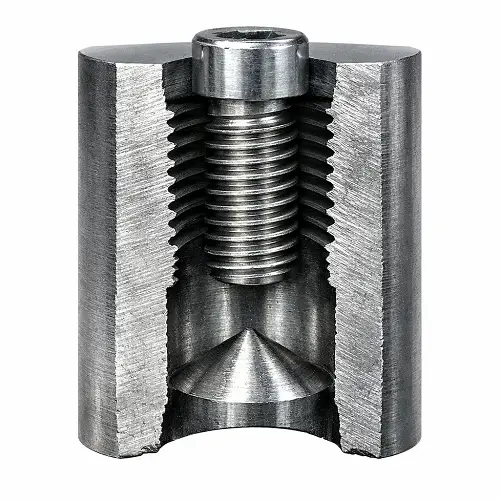
This is why a screw can bottom out before clamp load is reached even when the print appears correct. The nominal depth may be technically accurate, but the lower portion of the hole is not fully usable for threads or screw travel.
This gets worse on shallow blind holes. When the feature is short, the drill point consumes a larger percentage of the total depth. What looks acceptable in CAD can become marginal in production very quickly.
Real Problems Caused by the Wrong Bottom Assumption
A common problem is a threaded blind hole that looks deep enough on the drawing but delivers too little usable thread after drilling and tapping.
Another common problem is a set screw or fastener that bottoms out before the joint is actually clamped. The assembler feels resistance and assumes the connection is complete, but the screw has reached the lower geometry of the hole instead of generating full clamp load.
A third problem is a locating pin or mating feature that cannot seat as expected because the bottom is pointed rather than flat. The nominal hole depth may be correct, but the part does not travel as far as the designer assumed.
Shallow blind holes are especially sensitive. A few millimeters lost to the drill point can completely change the behavior of the feature.
How Machine Shops Create Different Blind Hole Bottom Shapes
A standard drilled blind hole normally ends in a pointed bottom because that is how the drill tip cuts. That is the most common and usually the most economical result.
If a flat or near-flat bottom is required, the machining method usually changes. Depending on diameter, material, and geometry, the shop may use a flat-bottom drill, end milling, interpolation, or another secondary process to create a flatter lower surface. Public references on blind-hole machining make the same distinction: conventional drills create conical bottoms, while flat-bottom drills or end mills are used when planar bottoms are needed.
This matters because flat-bottom blind holes are not equally practical across all sizes and depths. Small holes are less forgiving. Deep holes are less forgiving. Harder materials often make the requirement more demanding. A flat-bottom request that looks simple on a drawing may actually change the process significantly.
Hole Diameter, Depth, and Bottom Shape Must Be Reviewed Together
Blind hole bottom shape cannot be reviewed by itself. Diameter, depth, and function always change the answer.
Small-diameter holes are more sensitive because there is less room for drill-point height, less chip space, and less tolerance for design assumptions. Deep blind holes are more sensitive because chip evacuation, drilling stability, and bottom control all become harder. Blind-hole machining guidance widely notes that closed-end holes are more difficult to manage because chips accumulate at the bottom and bottom clearance becomes important.
This is also where machining capability matters. In reviewed applications, some blind-hole or related deep-hole features may reach the 160 mm to 180 mm depth range, depending on diameter, material, and geometry. At that depth, the conversation cannot stop at nominal depth. Drill stability, chip evacuation, bottom clearance, and usable depth all need to be reviewed together.
A long blind hole with a small diameter is not just a deeper version of a standard feature. It is a different machining problem.
What Should Be Specified on the Drawing?
If the bottom shape matters, the drawing should say so clearly.
The print should show total hole depth, but it should also make clear what portion of that depth is actually functional. If the hole is threaded, usable thread depth and total drill depth should not be treated as the same number.
If a flat bottom is required, that requirement should be explicit. If the lower part of the hole only needs to provide clearance and does not need to be flat, that should be understood too.
If a mating feature approaches the bottom closely, the print should make that relationship visible. If the design depends on bottom contact or controlled bottom clearance, the shop should not have to guess.
A good drawing does not just describe the hole. It explains what the lower part of the hole is supposed to do.
Practical Design Advice Before Releasing a Blind Hole
Do not assume blind hole bottoms are flat by default.
Leave extra room below usable threads in threaded blind holes. That space is not wasted. It is what keeps the feature functional.
Do not specify flat-bottom blind holes unless the function really needs them. If a drill-point bottom is acceptable, forcing a flat bottom only adds machining complexity and cost.
Review shallow blind holes carefully. They are often where bottom-shape assumptions create the biggest problems.
Review deep or small-diameter blind holes with the machine shop early. The tighter the geometry gets, the less forgiving the feature becomes.
Conclusion
Blind hole bottom shape in CNC machining is not a minor detail. It affects usable depth, thread performance, chip space, mating-part travel, and the real behavior of any feature that approaches the bottom of the hole.
A standard drill-point bottom is often perfectly acceptable when the design allows for it. A flat-bottom hole becomes more important when the lower region of the feature is truly functional. The right choice depends on how the hole is used, not on how simple it looks in CAD.
If a part includes shallow blind holes, threaded blind holes, bottom-contact features, or deeper blind-hole requirements, send the drawing to JeekRapid before production so hole depth, bottom shape, usable thread depth, and machining method can be reviewed together.
FAQs
What is the normal bottom shape of a blind hole in CNC machining?
The normal bottom shape of a drilled blind hole is usually a conical drill point, not a flat surface. A flat bottom normally requires a different tool or an additional machining step.
Why does blind hole bottom shape matter in threaded holes?
Because total hole depth is not the same as usable thread depth. Blind threaded holes need room for the drill point, thread runout, and bottom clearance, so ignoring the hole bottom shape can lead to short effective thread length or screws bottoming out early.
When should a flat-bottom blind hole be specified?
A flat-bottom blind hole makes more sense when the lower part of the hole is functionally important, such as for near-bottom seating, short usable depth, controlled bottom clearance, or designs that depend on bottom contact. A standard drill-point bottom is often enough when the lower region is only clearance.