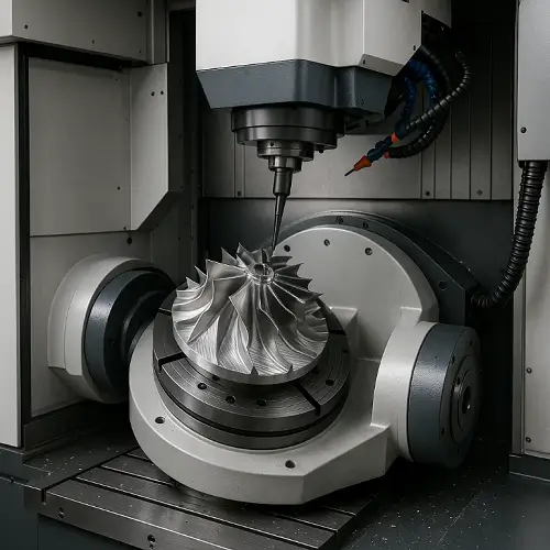
In the 21st century era of industrial advancement, the size and quality of holes in components often determine the performance of the entire part. From bearing housings in automotive engines to hydraulic passages in aerospace systems, poorly machined holes can lead to misalignment, leakage, or premature failure. When drilling fails to meet precision requirements, and boring or grinding proves too time-consuming or costly, reaming emerges as the most efficient finishing solution for engineers.
Reaming is the process of removing a minimal amount of material from a pre-drilled hole to improve its dimensions, geometry, and surface finish. This article provides a detailed overview of reaming fundamentals, process parameters, tool types, geometries, common industrial applications, troubleshooting methods, and engineering best practices.
What is Reaming?
Reaming is a finishing process in machining. A reamer is a multi-edge cutting tool that engineers use to slightly enlarge a previously drilled or bored hole to achieve tighter tolerances and a smoother surface. Drilling establishes the hole diameter, boring corrects hole position or diameter, and reaming is the final step to ensure precision.
Reamers can achieve tolerances conforming to ISO 286-1 standards (IT6–IT8) with surface roughness ranging from Ra 0.8–3.2 μm. In the United States, reamer classifications and dimensions are also defined in ASME B94.2. Reaming is essential for holes requiring precise fits, such as those for mounting pins, bushings, or bearings.
Process Parameters and Tolerances
Stock Allowance (machining allowance)
-
Steel: Radial 0.10–0.25 mm
-
Aluminum: Radial 0.15–0.30 mm
-
Cast Iron: Radial 0.05–0.12 mm
The machining allowance must be sufficient to enable smooth cutting by the reamer, but the cutting area should not be excessively large to prevent tool overload and breakage. Insufficient allowance causes friction, while excessive allowance leads to oversized holes and surface damage. Remember this!
Cutting Speed and Feed
| Material | Cutting Speed (m/min) | Feed (mm/rev) |
|---|---|---|
| Carbon Steel | 8–25 | 0.2–0.4 |
| Alloy Steel 4140 | 6–15 | 0.15–0.3 |
| Stainless Steel 304 | 6–12 | 0.15–0.25 |
| Aluminum 6061 | 30–60 | 0.3–0.8 |
| Titanium Ti-6Al-4V | 4–10 | 0.05–0.2 |
Tolerances and Finish
-
Typical hole quality: H6–H8 (ISO 286-1)
-
Surface roughness: Ra 0.8–3.2 μm
-
Improved roundness and cylindricity compared to drilling
Geometry and Design Features of Reamers
Reamers are designed not only for cutting but also to guide and stabilize themselves within the hole. Key geometric elements include: the guide section (where the tool gradually engages), the cutting section (for removing stock), and the cutting edge (for guiding and smoothing the hole surface). This combination achieves optimal precision and surface finish.
Chip flute design prioritizes simplicity and rigidity, making it ideal for machining cast iron and stable materials. Helical flutes enhance chip evacuation, making them the preferred choice for stainless steel or aluminum. Right-hand helical flutes push chips forward from through holes, while left-hand helical flutes pull chips backward from blind holes. Additionally, standard tapered groove types, such as Morse taper (DIN 228-1) or Brown & Sharpe taper, are widely adopted across various industries.
Types of Reamers
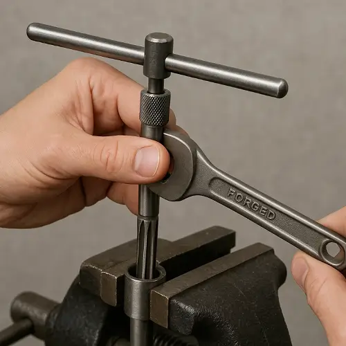
Hand Reamers
Hand reamers are manually rotated using a wrench. Featuring a long tapered lead, they facilitate direct tool guidance into the hole. Due to their reliance on operator control, slower speeds, and limited precision, they are suitable only for testing, maintenance, repair, or assembly adjustments—not for production.
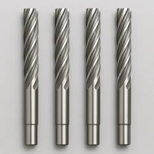
Machine Reamers
Machine reamers are used in drill presses, lathes, or CNC machining centers. They have a shorter lead and optimized geometry for controlled feed and speed. Straight flute designs suit cast iron machining, while spiral flutes enhance chip evacuation for stainless steel and aluminum.
Adjustable Reamers
Adjustable reamers feature blades that extend or retract within a limited range, accommodating non-standard hole sizes or fine adjustments. They are used in repair shops or prototyping. However, lacking the rigidity of solid reamers, they are unsuitable for production environments demanding consistent tolerances.
Taper Reamers
Taper reamers create tapered holes for tapered pins or sockets, commonly used for alignment and assembly. Achieving precise self-locking fits is critical. Standard taper reamers like Morse or Brown & Sharpe are widely used, while custom taper reamers can be tailored to specific requirements.
Solid Carbide and Coated Reamers
Solid carbide reamers are suitable for high-volume machining and demanding materials. They offer superior wear resistance compared to high-speed steel and can operate at higher cutting speeds. Coatings further enhance performance: TiAlN coatings withstand high temperatures in steel parts, DLC coatings reduce built-up edge in aluminum alloys, and PCD coatings deliver unmatched durability in high-abrasive alloy machining. Though higher in cost, they represent the most stable and cost-effective solution for production.
Engineering Applications
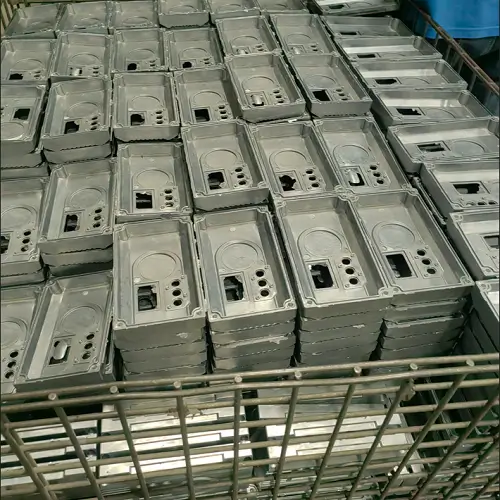
Reaming ensures tight fits and smooth internal bores. In automotive engineering, connecting rod holes are reamed to H7 tolerances to guarantee proper press-fit of bushings. Transmission housings often require reamed hydraulic passages to maintain sealing integrity. In aerospace, landing gear pin joints and hydraulic valve blocks rely on reamed holes for strength and leak prevention. Medical devices like stainless steel surgical instruments incorporate reamed pivot holes to ensure smooth, burr-free operation. In tool and die manufacturing, reaming guarantees precise alignment of guide pins and bushings, directly impacting mold performance and lifespan.
Common Issues and Troubleshooting
Oversized Holes
Typically result from excessive machining allowance, tool wear, or thermal expansion. Solutions include controlling pilot hole dimensions, replacing dull tools, and improving coolant flow.
Undersized Holes
Often caused by insufficient allowances or built-up edges in ductile materials. Engineers should increase allowances and consider coated reamers.
Poor Surface Finish
Usually indicates dull cutting edges or inadequate lubrication. Using sharp reamers and ensuring high-pressure filtered coolant prevents scoring and tearing.
Tapered or Flared Holes
Indicate unstable fixtures or spindle runout. Constant feed rates, rigid clamping, and proper tool holding promote consistency.
Burrs at Entry or Exit
Can be prevented by chamfering and reducing feed rates near breakout points.
Chatter (Vibration Lines)
Often signals excessive tool overhang or incorrect cutting speeds. Reducing overhang and lowering speed usually resolves the issue.
Engineering Best Practices
When specifying or setting up reaming operations, engineers should always allow the correct machining allowance and incorporate chamfers at entry and exit points to extend tool life. Tool geometry should match the material—straight flutes for hard materials, helical flutes for tough alloys. For low-volume production, high-speed steel reamers suffice, while carbide or coated reamers are better suited for high-volume manufacturing.
Precision toolholders (e.g., hydraulic or thermal shrink-fit systems) minimize runout, maintaining roundness within tolerances. Coolant must be abundant, clean, and directed toward the cutting zone. In-process inspection should use pass/fail gauges, while critical aerospace and medical applications require air gauges and coordinate measuring machines. Finally, engineers should proactively manage tool life, replacing reamers before excessive deflection occurs—the most common failure mode ending tool life.
FAQ
Q1: What tolerances can reaming achieve?
Typically IT6–IT8, with H7 being most common.
Q2: Can reaming correct hole positioning errors?
No. Reaming only improves dimensions and surface finish; boring is used to establish hole position.
Q3: How does reaming compare to honing?
Reaming is faster and less expensive but offers lower precision. Honing is used when Ra < 0.4 μm or higher roundness is required.
Q4: What allowance should be left before reaming?
0.10–0.25 mm for steel, 0.15–0.30 mm for aluminum, 0.05–0.12 mm for cast iron.
Q5: Can blind holes be reamed?
Yes, using left-hand twist reamers with chip flutes at the bottom.
Q6: Which coating is best suited for sticky materials like aluminum?
DLC and PCD coatings are highly effective against built-up edge (BUE).
Q7: Is reaming suitable for CNC machining centers?
Yes, CNC machining centers provide the rigidity and consistency required for high-precision reaming.
Reaming is a critical finishing process in manufacturing, bridging the gap between drilling and grinding. By carefully selecting tool types, geometries, and process parameters, engineers produce precise, smooth holes meeting stringent industrial standards.
JeekRapid integrates reaming technology into its CNC machining services, delivering high-quality bores for prototypes and production parts across automotive, aerospace, and medical industries. As an ISO 9001 and ISO 13485 certified manufacturer, JeekRapid applies international quality standards to every stage of machining. For more details, visit our CNC Machining Services page. If you have parts requiring machining, feel free to upload your CAD files and request a quote—we will respond within 24 hours.