5-axis machining is a high-precision CNC technology that controls five motion axes simultaneously to cut complex geometries. Compared with traditional 3-axis machining (X, Y, Z linear motion), a 5-axis system adds two rotary axes, allowing the tool to maintain an optimal cutting orientation. This reduces re-clamping, minimizes cumulative tolerance deviation, and improves both accuracy and efficiency when machining deep cavities, compound surfaces, and thin-wall structures.
For components with complex geometry, 5-axis machining is often the most reliable manufacturing approach.
What Are the Five Axes and How Do They Work
In a 5-axis machining center, the machine can move or rotate along five independent axes:
-
X axis – left–right linear movement
-
Y axis – front–back linear movement
-
Z axis – vertical movement
-
A axis – rotation around X
-
B axis – rotation around Y
Some machines use the C axis (rotation around Z) depending on the structural layout of the machine. The configuration may be spindle-tilting, table-tilting, split-type, or hybrid based on mechanical design and stiffness requirements.
Working Principle of 5-Axis Machining
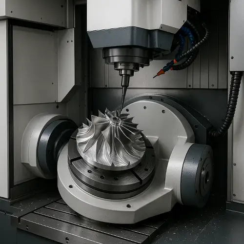
In simultaneous 5-axis machining, the tool orientation adjusts continuously to maintain a suitable contact angle with the workpiece. This allows tool access to areas unreachable in 3-axis setups and eliminates multiple manual fixturing steps.
The approach improves toolpath stability, surface interpolation accuracy, and reduces tool deflection—especially valuable for deep-cavity machining and lightweight aerospace components.
Advantages of 5-Axis Machining
Complete Complex Machining in a Single Setup
One clamping lowers datum alignment errors and prevents tolerance stack-up on multi-surface parts.
Reduced Machining Time and Overall Cost
Multi-angle accessibility shortens toolpath length and eliminates secondary fixtures.
Higher Surface Quality
Maintaining a more consistent cutting angle improves scallop height control on free-form contours.
Ideal for High-End and Difficult Geometry
Useful for turbine blades, blisks, impellers, orthopedic implants, and mold cores with organic shapes.
Better Tool Life
Stable tool loading reduces wear and improves chip evacuation—especially in hard-to-reach areas.
Disadvantages of 5-Axis Machining
Higher Equipment Cost
5-axis machining centers require precision rotary axes, thermal stability control, and high-end spindle design.
More Complex Programming
Simultaneous toolpaths require advanced CAM systems and experience with collision-avoidance strategies.
Higher Maintenance Requirements
Rotary axes need periodic calibration, backlash control, and tighter mechanical tolerances.
Materials Suitable for 5-Axis Machining
5-axis machining supports a wide range of engineering materials:
-
Metals – aluminum alloys, stainless steel, titanium alloys, nickel superalloys, copper
-
Plastics – POM, ABS, PC, PEEK, ULTEM
-
Composites – carbon fiber, fiberglass
-
Ceramics & stone – for high-precision tooling and medical components
The flexibility makes 5-axis suitable for aerospace, medical, optical, and precision mold industries.
Application Areas of 5-Axis Machining
-
Aerospace – turbine blades, blisks, engine housings, structural ribs
-
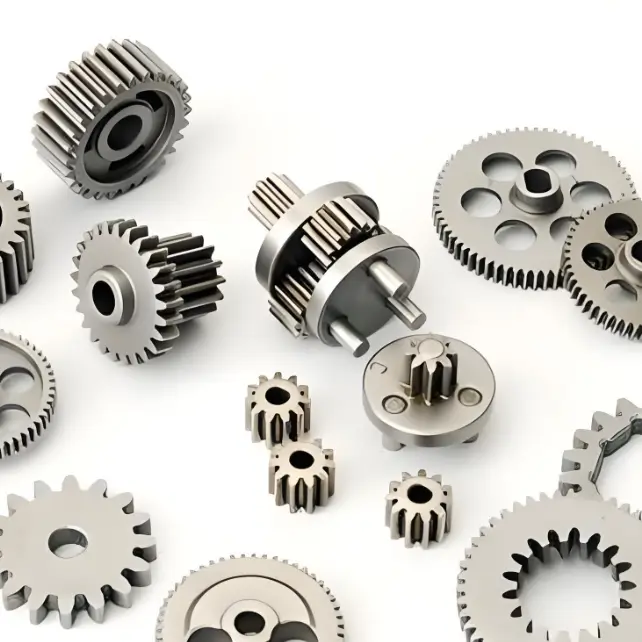
Automotive – engine parts, gearbox housings, prototype components
-
Medical – orthopedic implants, surgical tools, dental implants
-
Precision Molds – injection mold cores, complex cavities, EDM electrodes
-
Optical Equipment – lens mounts, alignment frames, precision housings
Differences Between 3-Axis, 4-Axis, 3+2-Axis, and 5-Axis Machining
| Machining Method | Number of Axes | Features |
|---|---|---|
| 3-axis machining | X, Y, Z | Suitable for simple geometry; requires multiple fixturings |
| 4-axis machining | X, Y, Z + A or B | Adds rotary motion; good for side surfaces |
| 3+2-axis machining | X, Y, Z + A/B fixed | Rotary axes lock at an angle; multi-side machining without continuous rotation |
| 5-axis machining | X, Y, Z + A, B or C | Full simultaneous rotation; ideal for complex surfaces and free-form contours |
5-Axis Machining Parameters and Tolerance Ranges
📘 Tooling Guidelines for 5-Axis Machining
| Item | Typical Value | Notes |
|---|---|---|
| Tool length / diameter ratio | 3:1 – 8:1 | Over 8:1 increases tool deflection risk |
| Ball end mill size | Ø3–Ø12 mm | Ideal for free-form surfaces |
| Spindle interface | HSK63 / HSK100 | High rigidity for multi-axis work |
| Tool approach angle | 10°–30° | Provides stable cutting load |
| Coolant type | External / high-pressure internal | Required for Ti and nickel alloys |
| Tool coating | TiAlN / AlTiN / DLC | Selected based on heat and material |
📘 General Cutting Parameter Ranges
| Material | Spindle RPM | Feed Rate (mm/min) | Depth of Cut | Notes |
|---|---|---|---|---|
| Aluminum | 12,000–25,000 | 1,500–4,000 | 0.2–1.0D | Good chip evacuation is key |
| Stainless Steel | 4,000–10,000 | 300–900 | 0.1–0.4D | Lower heat accumulation |
| Titanium | 2,000–6,000 | 120–400 | 0.05–0.2D | Requires high-pressure coolant |
| Carbon Fiber | 8,000–18,000 | 600–2,000 | Light | Avoid delamination |
| PEEK / PC | 6,000–18,000 | 1,000–3,000 | Light | Prevent melting on edges |
📘 5-Axis Tolerance Performance
| Feature Type | Typical Tolerance | Influencing Factors | Notes |
|---|---|---|---|
| 3D surfaces | ±0.01–0.03 mm | Tool length, thermal drift | Stable for free-form machining |
| Deep pockets | ±0.02–0.05 mm | Deflection, tool reach | Tool tilt reduces error |
| Precision holes | ±0.005–0.015 mm | Secondary fixturing | Use dedicated drilling strategy |
| Matching faces | ±0.01 mm | Toolpath stability | Good for optical housings |
| Mold cores | ±0.01 mm | CAM smoothing | Improves surface transition |
FAQs About 5-Axis Machining
Is 5-axis machining suitable for mass production?
It is more commonly used for high-precision, low-to-medium batch production where geometry complexity is high.
Do all 5-axis machines support the same type of parts?
Machine architecture varies; a head-tilting design handles larger workpieces, while cradle-type machines provide higher rigidity.
What is the typical accuracy level?
General performance is around ±0.005 mm, depending on tool reach, machine stiffness, and thermal behavior.
What CAM software is used?
Mastercam, PowerMILL, UG NX, HyperMill, and CATIA are widely used for simultaneous 5-axis toolpaths.
Why Use Jeek’s 5-Axis Machining
5-axis machining improves efficiency, accuracy, and manufacturability of complex structures. The combination of machine capability, toolpath strategy, and engineering experience determines final results.
JeekRapid operates advanced 5-axis machining centers with engineering teams experienced in complex geometry, aerospace-grade accuracy, mold-core machining, and precision medical components. This allows stable control of tolerances, clean surface transitions, and predictable machining performance.
Beyond 5-axis machining, JeekRapid provides multi-axis milling, CNC turning, prototype machining, and production machining for industries requiring high consistency.
For machining evaluations or quoting, the Jeek engineering team can support manufacturability reviews and material recommendations.