Rapid prototyping helps manufacturers turn product designs into physical samples before committing to production tooling or larger orders. These samples allow engineers to review the design, check assembly fit, and evaluate function while changes can still be made.
CNC machining, 3D printing, sheet metal fabrication, urethane casting, and rapid injection molding provide different ways to manufacture prototype parts. The right method depends on the material, geometry, quantity, and purpose of the sample. At JeekRapid, we manufacture custom metal and plastic prototypes from CAD models and drawings, helping customers select a suitable process and move from design to finished parts.
What Is Rapid Prototyping?
Rapid prototyping is a manufacturing approach used to produce physical models or sample parts from a digital design, usually a 3D CAD model. It allows a design to be examined and tested before it is finalized for production.
The term covers several manufacturing processes. Additive methods such as 3D printing build parts layer by layer. Subtractive methods such as CNC machining remove material from solid stock. Sheet metal processes cut and form sheet, while casting and molding reproduce parts using molds.
A prototype may represent the appearance, dimensions, assembly features, or working function of the intended product. It can be a single component or a group of parts assembled into a working model. Depending on its purpose, it may use the intended production material or a suitable substitute.
Rapid prototype manufacturing starts with a digital design and includes process preparation, part fabrication, any required finishing, and inspection before evaluation.
“Rapid” refers to shortening the time between a design and a physical sample. It does not mean every prototype can be completed within hours. Manufacturing time depends on the process, complexity, material availability, and any required tooling or finishing.
Why Is Rapid Prototyping Important in Product Development?
A design can be complete in CAD and still leave practical questions unanswered. Can the parts be assembled in the intended order? Is there enough room to install a fastener? Does a moving component remain clear of its surroundings? Will the selected material behave as expected?
Rapid prototyping gives engineers physical parts to investigate these questions before committing to production tooling or a larger order. Its value comes from discovering problems while the design can still be changed, then checking whether those changes solve them.
Faster Design Iteration
The first sample may reveal an awkward assembly sequence, an inaccessible screw, or a feature that needs more clearance.
With a physical prototype, the team can identify the problem, update the CAD model, and manufacture a revised part. Each revision addresses an observed issue rather than another assumption.
For example, a mounting hole may align correctly with its mating component but leave too little space for the tool needed to tighten the screw. Checking the hole position alone would miss the problem. Assembling the prototype makes it visible.
The next sample can confirm whether moving the hole or changing the surrounding geometry restores access. This gives the revision a clear purpose and a result that can be checked.
Finding Problems Before They Become Production Costs
A prototype adds an expense before production, but it can prevent a design issue from being repeated across an entire batch.
Changing a CAD model before the next machined or printed sample is generally more manageable than modifying a completed mold, reworking finished components, or replacing parts already purchased for assembly. The saving depends on the problem and when it is discovered.
Prototype spending should focus on the features that support the next decision. If the immediate question concerns assembly fit, final paint or texture may be unnecessary. If appearance or coating performance is being evaluated, the relevant finish belongs in the sample specification.
Earlier Functional Testing
CAD describes geometry, and simulation predicts behavior under defined assumptions. A physical prototype allows the team to compare those expectations with an assembled part under test conditions.
A mechanism may move freely by hand but bind when a load deflects its supporting components. Testing can help establish whether the problem comes from clearance, stiffness, alignment, or a combination of these factors.
The sample must represent the properties being evaluated. A plastic model can help assess layout, but it cannot establish the thermal performance of an aluminum production component. A suitable manufacturing method makes the test results more useful.
Clearer Decisions Between Teams
A physical sample gives engineering, purchasing, assembly, and manufacturing teams a common reference.
Engineering can evaluate function. Assembly staff can check handling and access. Purchasing can clarify which requirements must remain in the production quote. The manufacturer can identify features that need a different setup or inspection method.
This is particularly useful when requirements such as “smooth finish” or “easy assembly” are open to interpretation. Sample evaluation can turn those descriptions into specific observations and measurable acceptance requirements.
Approved changes should then be reflected in the drawing or specification so the next batch does not depend on someone remembering how the first sample was adjusted.
A More Informed Move into Production
After prototype evaluation, the team should know which features worked, which were revised, and which conditions have not yet been tested.
If production uses the same material and manufacturing route, much of the learning may carry forward. If production changes to injection molding, casting, or another process, additional validation may be necessary.
Rapid prototyping reduces uncertainty by answering specific questions before the next manufacturing commitment.
What Are the Different Types of Rapid Prototyping?
The main rapid prototyping processes for custom parts include CNC machining, 3D printing, sheet metal fabrication, urethane casting, and rapid injection molding.
Each method offers different options for geometry, materials, surface finish, and testing. Selecting between them requires understanding what each process can produce and how closely the sample needs to represent the final part.
CNC Rapid Prototyping
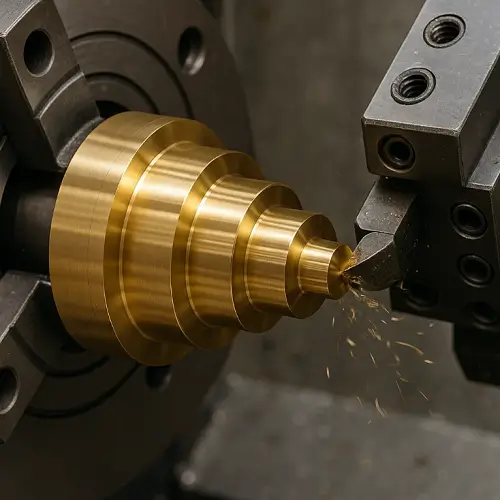
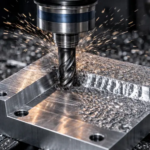
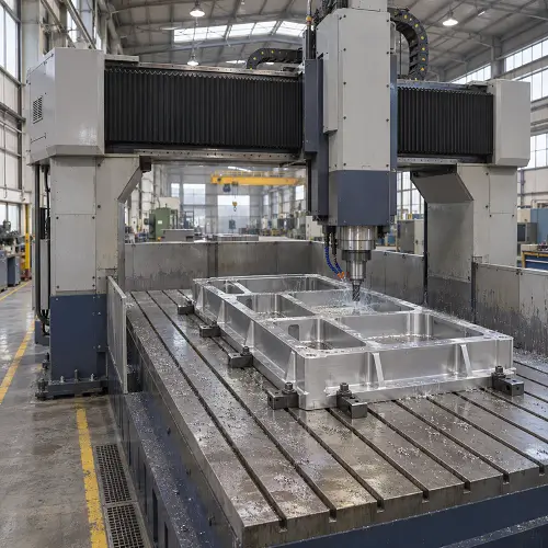
CNC machining creates parts by removing material from solid stock. Milling produces pockets, mounting faces, slots, and hole patterns. Turning produces shafts, bores, shoulders, grooves, and other rotational features. Some parts require both operations.
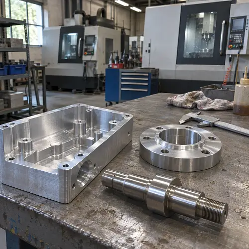
Rapid prototype machining is useful when a sample needs a specified metal or engineering plastic and controlled mating features. Common industrial prototyping applications include housings, brackets, shafts, fittings, and bushings used to evaluate equipment assemblies before production.
A machined sample can include the threads, bearing seats, sealing faces, and mounting features needed for assembly testing. These interfaces can be inspected against the drawing before delivery.
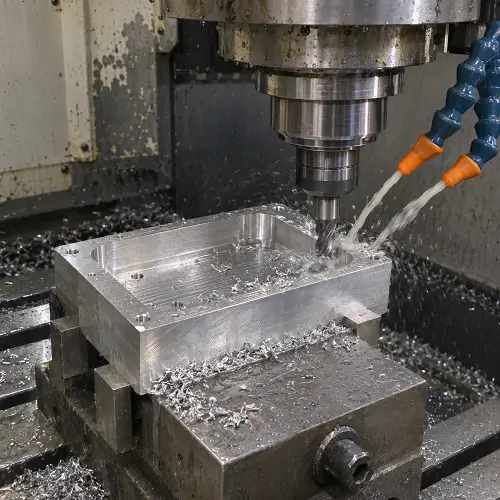
The material specification matters as much as the shape. A prototype intended to evaluate 6061-T6 aluminum should not use an unspecified aluminum alloy simply because it is easier to obtain.
The main geometric limitation is cutting-tool access. Closed internal passages, deep narrow cavities, and sharp internal corners may require another process or an agreed design change.
Our CNC prototyping review considers both the geometry and the features that need to be representative during testing. This helps determine whether machining alone can complete the sample or whether secondary operations are needed.
3D Printing
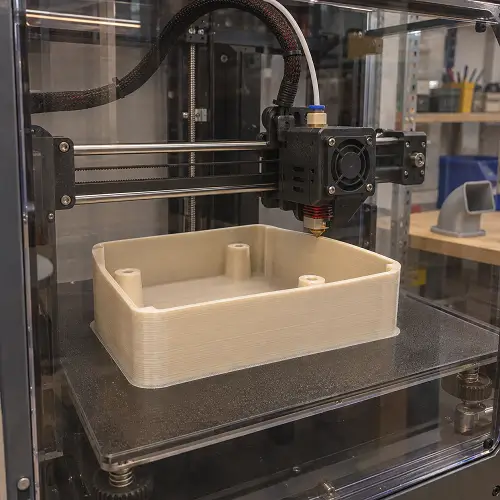
3D printing builds parts layer by layer. It can produce complex forms without machining every surface from a solid block.
Different printing technologies suit different requirements:
- FDM extrudes thermoplastic filament and supports layout models, assembly checks, and suitable functional components.
- SLA cures photopolymer resin and is useful for fine detail, smooth surfaces, and application-specific test parts.
- SLS and MJF produce polymer parts from powder and are used for ducts, housings, clips, and complex functional assemblies.
- Metal additive processes can manufacture complex metal geometry, often followed by heat treatment, support removal, or machining.
Printed prototypes are not limited to appearance models. Suitable materials and processes can support functional evaluation, but their properties depend on build orientation, processing conditions, and post-treatment.
Internal features also need review. Powder, uncured resin, or supports must be removable where the process requires it. A cavity that can be drawn in CAD is not automatically practical to manufacture.
For 3D printed prototypes, the process should be selected around the geometry and test conditions rather than the general label “3D printing.”
Sheet Metal Prototyping
Sheet metal prototyping manufactures parts from sheet using cutting, bending, joining, and hardware-installation processes.
It suits panels, folded brackets, covers, control boxes, and equipment enclosures. Laser-cut prototypes can establish flat profiles and hole layouts, while bending creates the finished three-dimensional structure.
When the production part will use formed sheet, this route can reveal bend interference, fastener access, panel stiffness, and assembly problems. A solid printed model may reproduce the outside shape without representing those manufacturing details.
Sheet grade and thickness should match the evaluation. Changing either can affect stiffness, bend behavior, and the position of formed features.
A flat blank alone does not validate a finished enclosure. Sheet metal fabrication may also need to include installed hardware, welding, deburring, and finishing so the sample represents the intended assembly.
Urethane Casting
Urethane casting produces parts from polyurethane casting resin using a mold, commonly a silicone mold made from a master pattern. Vacuum processing helps reduce trapped air in suitable casting workflows.
It is useful when several similar plastic samples are needed for demonstrations, assembly trials, or selected functional evaluations. Common parts include covers, housings, grips, and flexible components.
The master pattern influences the detail and surface finish reproduced in the cast parts. Marks left on the master can appear repeatedly, so preparing the pattern is part of the manufacturing process.
Casting materials need careful identification. An ABS-like polyurethane is not ABS, and a rubber-like resin is not automatically equivalent to a specified production elastomer.
Vacuum casting requires a master and mold before repeated parts can be produced. It may suit a group of samples with stable geometry, while direct machining or printing may be more practical for a single part that is still changing.
Rapid Injection Molding and Prototype Tooling
Rapid injection molding uses a mold to produce samples from a selected molding resin. Prototype tools may use aluminum or steel, depending on the part, resin, quantity, and expected revisions.
This method is useful when the sample needs to reflect injection-molding behavior. It can support evaluation of molded snap-fits, specified resin grades, shrinkage, warpage, and other process-dependent characteristics.
Rapid prototype tooling still requires engineering work. Gates, parting lines, ejection, cooling, and any moving mold features must be considered before samples can be produced.
It becomes more attractive when the design is stable enough to justify tooling and when other methods cannot answer the required questions.
Prototype and production molds may differ in cavity count, gating, cooling, or construction. Consequently, injection-molded samples should be evaluated with those differences understood.
How Do You Choose the Right Rapid Prototyping Method?
Choose the method around what the sample must demonstrate. Material, geometry, interfaces, and quantity then narrow the options.
| Your Main Requirement | Method to Consider | What Needs Checking |
|---|---|---|
| Review shape, packaging space, and access | Suitable polymer 3D printing | Whether the material and surface quality are sufficient for the review |
| Test metal threads, bores, or mating surfaces | CNC machining | Tool access, material condition, and inspection requirements |
| Evaluate bent brackets or sheet enclosures | Sheet metal prototyping | Formed dimensions, bend access, seams, and installed hardware |
| Produce several similar plastic samples | Urethane casting | Resin suitability, master quality, and mold life |
| Manufacture complex internal geometry | Suitable additive manufacturing | Support or trapped-material removal and finishing operations |
| Evaluate a specified resin in a molded part | Prototype injection molding | Tooling requirements and differences from future production |
Start with the Sample’s Purpose
An appearance review, an assembly check, and a load test can require different versions of the same part.
For an appearance review, shape, color, and texture may take priority. An assembly check needs representative interfaces and clearances. A load test needs suitable material, geometry, and manufacturing condition.
Define the decision the prototype must support before selecting a process. This prevents paying for unnecessary features while overlooking the ones that affect the result.
Identify the Features That Control Fit
A general process accuracy figure does not establish whether your part can be assembled.
A housing may depend on mounting-hole position and cover flatness. A shaft may depend on bearing journals and their alignment. Those features should be identified on the drawing.
For example, a bearing seat specified at ±0.001 in, approximately ±0.025 mm, needs focused machining and inspection. A non-mating outside surface may not require the same control.
The process should be assessed against these requirements rather than a single tolerance applied to the whole part.
Consider Design Changes and Quantity Together
If the design is still changing, machining or printing can avoid repeated mold modifications.
Once several identical samples are required, casting or prototype molding may become worth considering. However, quantity alone does not determine the best route. Part size, complexity, material, finishing, and tooling work all affect the decision.
Compare the complete manufacturing route, including preparation and inspection, rather than only the machine cycle.
Allow Different Parts to Use Different Methods
An assembly does not have to use one prototyping process throughout.
A machined shaft, printed cover, and bent bracket may provide an appropriate combination for a working prototype. Each component can use the process that best represents its function.
The interfaces between them still need coordinated dimensions and inspection. Individually acceptable parts may fail to assemble if their mating requirements are inconsistent.
CNC Machining vs 3D Printing: Which Is Better for Prototypes?
CNC machining is often appropriate when a prototype needs a specified stock material and controlled machined interfaces. 3D printing is often attractive when complex geometry or frequent design revisions make machining less practical.
Neither method is automatically faster, cheaper, or more accurate for every part.
When CNC Machining Is the Better Fit
Consider CNC when the sample requires metal threads, accurate bores, flat mating surfaces, or a particular engineering plastic available as stock.
It is also useful when the test depends on the properties of a specified alloy and temper. A machined aluminum bracket can provide a more relevant load-test sample than the same geometry printed in a polymer.
However, a machined part does not automatically represent a future casting, forging, or molded component. The manufacturing route can affect material structure and finished behavior.
When 3D Printing Is the Better Fit
Consider printing when the design includes geometry that is difficult to reach with cutting tools or when early revisions need to be produced without extensive machining preparation.
Complex ducts and internal features are common reasons to assess additive manufacturing. Printed parts can also support functional tests when the selected material and process are suitable.
The choice should account for loading direction, temperature, surface requirements, and post-processing. “Printed” does not describe one consistent set of properties.
When Combining Both Methods Makes Sense
A printed metal body may need its bearing seats or sealing faces machined. A printed polymer housing may need inserts for repeated screw assembly.
Combining methods can preserve geometric freedom while controlling selected interfaces. These operations should be planned together so enough material and access remain for finishing.
What Materials Are Used in Rapid Prototyping?
Rapid prototyping materials include metals, engineering plastics, photopolymer resins, and flexible materials. Available choices depend on the manufacturing method.
Use the intended production material when its properties are necessary for the evaluation. A substitute can be useful for an earlier check, provided its limitations are understood.
Common Materials for CNC Rapid Prototyping
| Material | Main Characteristics | Typical Prototype Parts | What to Consider |
|---|---|---|---|
| Aluminum 6061 / 7075 | Low weight; 6061 suits many general applications, while 7075 offers higher strength in appropriate tempers | Housings, brackets, plates, and structural parts | Specify alloy and temper |
| Stainless Steel 304 / 316 | Corrosion resistance; 316 generally offers better resistance in chloride environments | Fittings, shafts, housings, and fluid-handling parts | Suitability depends on the exposure conditions |
| Carbon Steel / Alloy Steel | Strength and wear performance depend on grade and heat treatment | Pins, shafts, gears, and loaded components | Heat treatment can affect dimensions and performance |
| Brass / Copper | Brass generally machines readily; copper offers high thermal and electrical conductivity | Connectors, terminals, fittings, and thermal parts | Select the alloy for the required conductivity and strength |
| ABS | Tough plastic used for many enclosure prototypes | Covers, housings, and mounting components | Machined samples do not reproduce molding-related behavior |
| POM / Acetal | Low friction and good machinability | Bushings, gears, guides, and sliding parts | Check load, temperature, and wear requirements |
| PC | Toughness and impact resistance; transparent grades are available | Protective covers and housings | Clarity requires suitable finishing; residual stress matters |
| PMMA / Acrylic | Transparency and polishability | Windows, light guides, and appearance models | More brittle than PC |
| PA / Nylon | Useful friction and wear properties | Rollers, bushings, and mechanical components | Moisture conditioning affects dimensions and properties |
| PEEK | High-temperature capability and chemical resistance | Demanding mechanical and electrical prototypes | Higher material cost; specify the appropriate grade |
Common Materials for Other Rapid Prototyping Methods
| Manufacturing Method | Common Materials | Suitable Prototype Uses | What to Consider |
|---|---|---|---|
| FDM 3D Printing | PLA, ABS, PETG, PA, TPU | Layout models, assembly checks, and selected functional parts | Orientation, layer bonding, and print settings affect performance |
| SLA 3D Printing | Standard, tough, high-temperature, and flexible photopolymer resins | Detailed parts, appearance samples, and selected functional tests | Formulation and post-curing determine properties |
| SLS / MJF 3D Printing | PA12, PA11, and selected filled or flexible grades | Ducts, housings, clips, and complex assemblies | Availability differs by process; finishing may be needed |
| Metal 3D Printing | Selected aluminum, stainless steel, and titanium alloys | Complex metal prototypes and internal features | Heat treatment, support removal, and machining may be required |
| Sheet Metal Prototyping | Aluminum sheet, mild steel, and stainless steel | Panels, brackets, covers, and enclosures | Grade, thickness, bend radius, and forming direction matter |
| Urethane Casting | Rigid and flexible polyurethane casting resins | Repeated plastic samples, grips, housings, and appearance parts | Substitute resins may only reproduce selected properties |
| Rapid Injection Molding | Suitable grades of ABS, PC, PP, PA, POM, TPE, and other molding resins | Molded functional samples and pre-production parts | Resin grade, tooling, and processing affect the result |
These are material options across the methods, not a guarantee that every material suits every geometry or manufacturing setup.
For plastic rapid prototyping, distinguish the polymer name from the finished part’s behavior. CNC-machined ABS, FDM-printed ABS, and an ABS-like casting resin should not be assumed to produce equivalent test results.
For metal prototyping, specify the alloy and material condition required for the test. Temper, heat treatment, and finishing can affect performance even when the prototype matches the CAD geometry.
How Long Does Rapid Prototyping Take?
Rapid prototyping can take days or weeks. Direct machining and printing avoid mold manufacture, while casting and injection molding add pattern or tooling stages before samples can be completed.
Some straightforward CNC projects can target approximately 3–5 business days of manufacturing after the drawing, material, and production schedule are confirmed. Complex features, special materials, finishing, or additional inspection can extend that window. Shipping time is separate.
The useful deadline is when the sample will be ready for evaluation, not when the machine stops.
Printed parts may still need cleaning, support removal, curing, or finishing. Machined parts may need deburring, treatment, and inspection. Molded samples may require a tooling adjustment before they meet the agreed requirements.
To avoid unnecessary delays, confirm the drawing revision and required interfaces before manufacturing. Resolve material substitutions early, and specify which finishing operations are necessary for the current evaluation.
If the deadline is fixed, we can assess whether a simpler first-stage sample will answer the immediate question. Any change to the sample’s requirements should be agreed before production.
Can Rapid Prototypes Be Used for Functional Testing?
Yes, when the sample represents the properties and interfaces relevant to the test.
A prototype can be suitable for one evaluation and unsuitable for another. A model that establishes connector access may not be appropriate for a temperature, impact, or pressure test.
Assembly and Movement
Use the actual mating components where practical. Check fastener installation, clearances, movement, and disassembly access.
One sample assembly proves only that the tested parts fit together. It does not establish that every combination within the permitted dimensional variation will assemble successfully.
Record any hand fitting or adjustment. Those changes may identify a requirement that needs to be added to the drawing.
Load, Heat, and Wear
Match the sample to the conditions being evaluated.
A thicker prototype wall can hide a weakness in a thinner production design. A different heat treatment can change a metal part’s response to load. Moisture exposure can alter the dimensions and behavior of some polymers.
Document the sample’s material, manufacturing condition, and test conditions so the results can be interpreted correctly.
Sealing and Fluid Handling
A leak or pressure test depends on more than overall shape.
Sealing faces, grooves, threads, material integrity, and the mating seal can all affect performance. A prototype used for this purpose needs those features manufactured and inspected appropriately.
A printed model suitable for checking pipe routing may require another process or material before it can support a meaningful pressure test.
Appearance and Handling
Finished samples can be used to evaluate color, texture, transparency, and grip.
However, painted color does not necessarily reproduce molded-in color, and a polished machined surface does not automatically represent a future mold texture.
Approve the characteristics that the sample actually demonstrates, and retain an agreed reference where appearance is part of later acceptance.
Can Rapid Prototyping Support Low-Volume Production?
Yes. CNC machining, additive manufacturing, sheet metal fabrication, casting, and molding can support suitable low-volume projects.
Approved prototypes may lead to parts for field trials, equipment installation, or early deliveries. At that stage, consistency between parts becomes more important than the success of a single sample.
Before repeat manufacturing, establish the approved revision, material condition, finished dimensions, and inspection requirements. Any manual changes made during prototype assembly should be resolved in the design or manufacturing plan.
For low-volume CNC machining, the same general route may continue with workholding and production planning adapted to the quantity.
If the manufacturing method changes, review the design again. Moving from machined plastic to injection molding introduces draft, shrinkage, gating, and ejection considerations. Moving from a printed metal sample to a casting may change material structure and dimensional behavior.
We can review both stages together: what the first samples need to demonstrate and which requirements must be maintained for subsequent orders.
Conclusion
Rapid prototyping helps turn a design into evidence that can guide the next manufacturing decision. CNC machining, printing, sheet metal, casting, and molding each offer useful options, but the right choice depends on the part and the purpose of the sample.
JeekRapid provides rapid prototyping services for custom metal and plastic components, from initial samples to suitable low-volume production. Upload your CAD model and drawing for a quote and tell us what you need to evaluate. We can review the geometry, material, quantity, and finishing requirements, recommend a manufacturing route, and confirm the delivery schedule.