A lot of parts look simple when you first open the drawing. There may be a few diameters, a central hole, some flats, maybe a slot or two. Then the real manufacturing question shows up: is this part better for a CNC lathe or a milling machine?
That choice affects more than people think. It affects machining cost, setup time, tolerance strategy, and sometimes whether the process feels natural or forced. A part that belongs on a lathe can become unnecessarily expensive if it is pushed toward milling. A part that really needs milling can become awkward if someone assumes “it looks round, so it must be a lathe part.”
The difference is not about which machine is more advanced. The difference is about shape. A CNC lathe is built around rotating parts. A milling machine is built around rotating tools. Once that is clear, the rest becomes much easier to understand.
What Is a CNC Lathe?
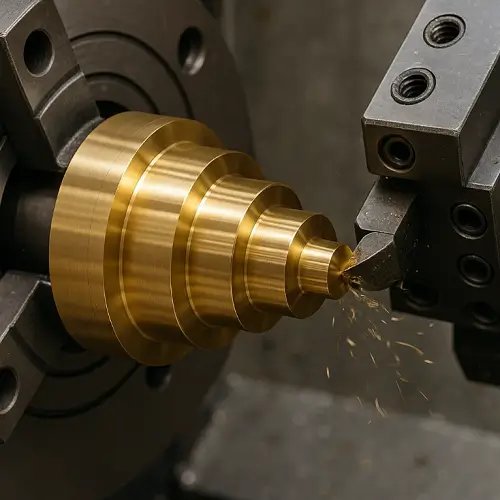
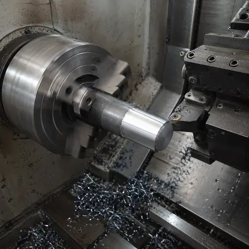
A CNC lathe rotates the workpiece while the cutting tool moves against it. That makes it the natural choice for parts built around one center axis.
Typical lathe parts include shafts, pins, bushings, spacers, rollers, sleeves, threaded round fittings, and many turned housings. If the part keeps the same general profile as it rotates around its centerline, a lathe usually handles it efficiently.
Lathes are especially good at making outside diameters, inside diameters, steps, grooves, chamfers, faces, and threads on round parts. For a true cylindrical part, turning is usually the first process worth considering.
What Is a Milling Machine?
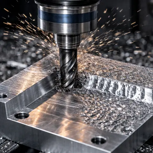
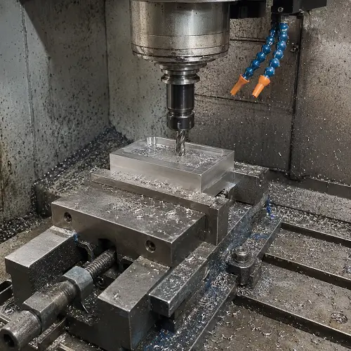
A milling machine rotates the cutting tool while the workpiece stays fixed or moves along controlled axes. That makes milling a better fit for parts defined by faces, slots, pockets, contours, and features on multiple sides.
Typical milled parts include brackets, plates, housings, manifolds, fixture blocks, and irregular components with features that change from one face to another. Milling is also the more natural choice for bolt patterns, side holes, keyways, pockets, and custom outer shapes.
If the part is driven more by surfaces and contours than by one central axis, milling usually makes more sense.
CNC Lathe vs Milling Machine: What Is the Main Difference?
The main difference is simple.
On a lathe, the part rotates.
On a milling machine, the tool rotates.
That changes the kind of geometry each machine handles best. A lathe prefers rotationally symmetric parts. A milling machine prefers flat, multi-face, or irregular parts.
This is why machine choice should start with the overall geometry, not with one small feature. A round shaft with one cross hole is still usually a lathe-first part. A rectangular housing with one central bore is still usually a milling-first part. The dominant shape matters more than the detail that catches attention first.
Advantages and Limitations of a CNC Lathe
Main advantages of a CNC lathe
A CNC lathe is usually the more efficient choice for true round parts. The machine naturally produces diameters, shoulders, tapers, grooves, bores, and threads around one axis. When the part is rotationally symmetric, that process is direct and economical.
A lathe also handles coaxial features naturally. If a part needs several turned diameters to stay related to the same centerline, turning is often the cleanest way to get there.
For many shafts, bushings, pins, and threaded round components, a lathe is simply the right machine from the beginning.
Main limitations of a CNC lathe
A lathe is not the best choice for parts dominated by flats, pockets, side contours, bolt patterns, or non-symmetric outer shapes. More advanced turning centers with live tooling can add extra capability, but that does not change the basic truth: once the part stops behaving like a round part, the process becomes less natural.
This is where cost and complexity start to climb. A part that is mostly prismatic or irregular usually should not be treated like a lathe-first component.
Advantages and Limitations of a Milling Machine
Main advantages of a milling machine
A milling machine is much more flexible with part shape. Flats, pockets, slots, side holes, contours, and multi-face features are all normal milling work.
Milling is also the stronger choice for parts that need features on several sides or features that do not repeat around one centerline. Brackets, plates, housings, and many custom mechanical parts are easier to machine on a mill because the process is built around controlled motion in multiple directions.
When the part geometry is driven by surfaces and changing profiles, milling usually wins.
Main limitations of a milling machine
A milling machine can make round features, but it is not always the most efficient path for a part that is fundamentally cylindrical. If the whole part is a shaft, sleeve, pin, or turned spacer, forcing that work into a milling-heavy route usually adds cost without adding value.
That is the practical limitation of milling. It is flexible, but flexibility is not always the cheapest answer when the part naturally belongs on a lathe.
What Parts Are Best for a CNC Lathe?
A CNC lathe is usually best for parts such as:
- shafts
- pins
- bushings
- spacers
- rollers
- nozzles
- threaded round fittings
- sleeves
- hubs with rotational symmetry
These parts share the same basic trait: the main shape is built around one axis.
A stepped steel shaft is a good example. If the part has turned diameters, grooves, threads, and a center bore, that is naturally a lathe-first part. The whole design is built around rotation. Milling might still appear later for a flat or a cross hole, but the base geometry belongs to turning.
What Parts Are Best for a Milling Machine?
A milling machine is usually best for parts such as:
- brackets
- plates
- housings
- manifolds
- fixture blocks
- custom mechanical blocks
- parts with pockets and slots
- parts with multiple machined faces
These parts are not defined by one rotating axis. They are defined by surfaces, positions, and shapes that change from side to side.
A rectangular aluminum bracket is a simple example. If the part includes mounting holes, side slots, a shallow pocket, and two machined faces that need to stay square to each other, that is clearly a milling part. Even if one bore is important, the whole part still behaves like a milled component.
Why Round Parts Usually Favor a Lathe
When a part is truly round, a lathe usually handles the geometry more naturally than a mill. Outside diameters, concentric bores, shoulders, grooves, end faces, and threads can all be machined in a way that matches the part’s basic form.
This is not only about speed. It is also about process logic. A rotationally symmetric part wants to be machined around its axis. A lathe is built for exactly that.
That is why shafts, bushings, and spacers are often quicker to quote, easier to fixture, and more economical to produce on a lathe.
Why Flat and Multi-Side Parts Usually Favor Milling
Milling becomes the better fit when the part is no longer driven by one axis. Once the drawing includes flats, pockets, slots, bolt patterns, side holes, or different shapes on different faces, a milling machine usually has the advantage.
The reason is simple. Milling handles changing geometry better. The tool can approach the part from different directions and follow whatever contour the design requires.
That is why housings, plates, manifolds, and brackets almost always lean toward milling unless the drawing also includes a very strong turned core feature.
CNC Lathe vs Milling Machine in Cost, Speed, and Efficiency
Cost and speed depend less on the machine name and more on whether the machine fits the geometry.
A lathe is usually more efficient when the part is round and centered around one axis. Setup is simpler, the cutting path is natural, and the machine is doing work that suits its design.
A milling machine is usually more efficient when the part has many surfaces, multiple sides, or non-round geometry. Trying to force those parts into a turning route often creates unnecessary setup work.
The wrong machine choice increases cost because the shop ends up working around the part instead of machining it naturally.
Quick Comparison
| Point | CNC Lathe | Milling Machine |
|---|---|---|
| Main cutting motion | Workpiece rotates | Tool rotates |
| Best overall shape | Round, rotationally symmetric parts | Flat, multi-face, irregular parts |
| Strongest features | Diameters, threads, grooves, shoulders, bores | Pockets, slots, faces, side holes, contours |
| Efficiency advantage | Cylindrical parts | Prismatic and complex geometry |
| Main limitation | Less natural for complex non-round parts | Less efficient for true turned parts |
Can One Part Need Both Turning and Milling?
Yes. Many real parts do.A turned round body may need milled flats, cross holes, keyways, or wrench features after the main turning is done. A milled housing may need a precision bore or turned round interface that is easier to control with turning.
A common example is a round stainless fitting with external threads, a hex flat section for wrenching, and two cross holes. That is not purely a lathe part and not purely a milling part. It is a lathe-first part with secondary milling features.
This is why machine choice should not be based on one feature alone. The whole part has to be considered.
How to Tell Which Process Fits Your Part Better
A few direct questions usually make the answer clearer.
If the part is mostly round and stays the same around its axis, it is probably more like a lathe part.
If the part changes shape from side to side, it is probably more like a milling part.
If the drawing is defined mainly by diameters, shoulders, and threads, turning is often the stronger choice.
If the drawing is defined mainly by faces, holes, slots, pockets, and contours, milling is usually the better route.
Another useful question is this: does the geometry repeat as the part rotates, or does it change from one face to the next? That one question often gets you close to the right answer very quickly.
Common Mistakes When Choosing Between a Lathe and a Milling Machine
One mistake is assuming every part with a round section belongs on a lathe. A part may start from round stock and still end up being milling-dominant if the final geometry is mostly flats, slots, and side features.
Another mistake is assuming every part with holes belongs on a mill. A shaft with a few secondary holes is still often a turning-first part.
A third mistake is choosing the machine based on one feature instead of the whole part. The dominant geometry matters more than the small detail that first catches the eye.
The last common mistake is ignoring combined processes. Many real components are not purely lathe parts or purely milling parts. Treating them that way too early can lead to bad quoting assumptions and awkward process routes.
Practical Tips Before Requesting a Quote
The drawing should show the real functional geometry clearly. Turned diameters, milled flats, side holes, slots, pockets, and threads should all be easy to identify.
It also helps to think in terms of dominant geometry. If the part is mainly rotational, say so. If the critical function depends on multi-face milling features, that matters too.
Most important, do not try to force the process too early based on one feature. A part with both turned and milled features often needs a combined route, and that route is easier to plan when the manufacturing team reviews the complete geometry first.
Conclusion
CNC lathes and milling machines do not solve the same geometry problem in the same way. A lathe is usually the better choice for rotationally symmetric parts such as shafts, pins, bushings, spacers, and threaded round components. A milling machine is usually the better choice for flat, multi-face, and irregular parts such as brackets, housings, plates, and blocks with pockets or side features.
Many real components use both processes, and that is exactly why the right process should be chosen from the full part geometry, not from one isolated feature. If you are reviewing a drawing and are not fully sure whether the part is more suited to turning, milling, or a combined route, upload your CAD file to JeekRapid for a manufacturing review and quote. A quick process review at the quoting stage can help avoid the wrong setup path, reduce unnecessary machining cost, and move the part toward production faster.