Some rotating parts look fine until they are checked in setup, inspection, or assembly. The diameter may be within tolerance, yet the part still wobbles. A drilled hole may come out larger than expected even though the drill size was correct. Tool life may drop for no obvious reason. In machining, those problems often trace back to runout.
Runout is not just a GD&T symbol on a drawing. It is a real machining and rotation problem that affects part quality, tool life, vibration, and final performance. Shops deal with runout on the machine. Inspectors deal with it on the print. If those two sides are not understood together, people end up chasing diameter while missing the real source of the problem.
Runout is the amount of wobble or variation seen when a tool or part rotates around a reference axis. In machining, runout can make holes cut oversize, reduce tool life, worsen surface finish, and create vibration. On drawings, circular runout controls one section at a time, while total runout controls the full surface during rotation.
What Is Runout in Machining?
Runout is the amount of variation seen when a rotating feature moves around its intended axis. In simple shop language, runout is how much a tool or part fails to rotate true.
That matters because runout is not just a size issue. A shaft can measure the correct diameter and still run poorly. A cutter can have the correct nominal size and still machine badly if it is not rotating concentrically. This is why runout often shows up as a performance problem before it shows up as a simple dimensional one.
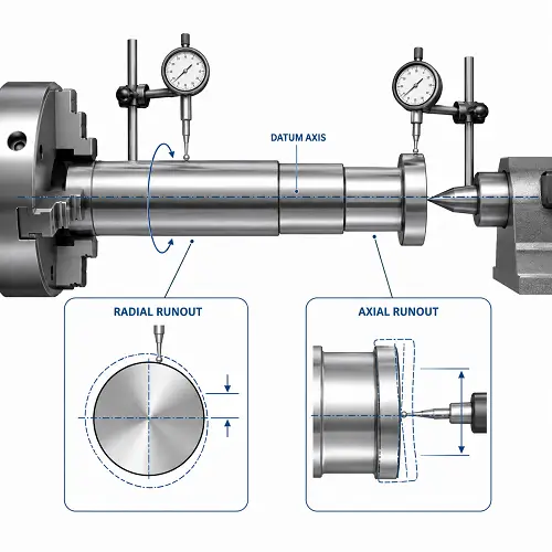
Radial Runout vs Axial Runout
Runout usually appears in two basic forms: radial and axial.
Radial runout
Radial runout happens when the rotating feature is offset from the intended axis of rotation. The part or tool is spinning, but not truly around its own centerline. One common shop example is a drill held slightly off-center in the holder. The drill still cuts, but the hole may come out larger than the drill size because the tool is orbiting slightly as it rotates.
Axial runout
Axial runout is different. Here the feature is tilted rather than simply offset. This is more obvious on end faces, shoulders, and surfaces that should run flat during rotation. A face may look acceptable standing still, then show wobble once the part rotates.
Radial vs Axial Runout at a Glance
| Type | What is moving wrong | Typical shop symptom |
|---|---|---|
| Radial runout | Feature is offset from the intended rotation axis | Oversized holes, uneven cutter loading, wobble in cylindrical rotation |
| Axial runout | Feature is tilted relative to the intended rotation axis | End-face wobble, uneven seating, error that grows with distance |
Why Runout Matters in Machining
Runout matters because it changes how the tool or part behaves while rotating.
On the cutting side, runout means some teeth do more work than others. That drives uneven wear, poorer finish, and shorter tool life. On the part side, runout causes wobble, vibration, unstable rotation, and poor bore or journal behavior in service.
This is why runout is not just a measurement topic. It affects:
- hole size
- surface finish
- vibration
- bearing performance
- cutting stability
- tool life
- final assembly behavior
A part can still measure close in size and perform badly if runout is not controlled.
Common Causes of Runout in Machining
Runout usually comes from setup, tooling, or the relationship between the feature and its datum.
Toolholder or spindle error
If the holder, spindle, or collet is not running true, the cutter will not run true either. Even a good tool can cut badly in a poor holder.
Poor workholding or chucking
If the part is not clamped correctly, the rotation axis used in machining may not match the axis the feature is supposed to follow.
Re-clamping between operations
A part may be machined in one setup, then re-chucked for another operation. If the second setup does not match the intended datum axis, runout can appear even when size looks acceptable.
Dirt, chips, or damaged contact surfaces
A small chip under a toolholder or part seat can be enough to create measurable runout.
Datum mismatch between machining and inspection
This is a common source of confusion. The shop may machine a feature from one reference, while inspection checks runout from another. The part then “fails runout” even though the machinist thought the process was correct.
Tool Runout vs Part Runout
Tool runout and part runout are related, but they are not the same problem.
Tool runout is about the cutter not rotating true. This affects hole size, finish, and cutter wear.
Part runout is about the finished feature not rotating true relative to its datum axis. This affects how the part performs in service or inspection.
If a drill cuts an oversize hole, tool runout may be the cause. If a finished shaft wobbles in rotation, the problem is usually part runout. Treating both problems the same way leads to wasted effort.
Runout in GD&T
In GD&T, runout is a datum-based control. It checks how a surface behaves as the part rotates about a datum axis.
That is what makes runout different from a simple size tolerance. Diameter tells you how large the feature is. Runout tells you how that feature behaves during rotation relative to a reference axis.
This is why runout is often used on shafts, journals, tapered rotating features, and other parts where rotational behavior matters in function.
Circular Runout vs Total Runout
This is one of the most important distinctions in the whole topic.
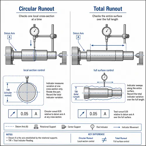
Circular runout
Circular runout is local control. It checks one cross-section at a time as the part rotates about the datum axis. Each section is evaluated separately.
Total runout
Total runout is full-surface control. It checks the entire surface while the part rotates and the indicator sweeps along the feature. This makes it stricter than circular runout because it looks at the full surface as one functional system.
Circular vs Total Runout
| Control | What it checks | Better fit for |
|---|---|---|
| Circular runout | One cross-section at a time | Short features, local bearing seats, localized rotational control |
| Total runout | Entire surface in one overall sweep | Long shafts, tapered fits, full-length journals, end-to-end surface consistency |
Why a Part Can Pass Circular Runout but Fail Total Runout
This is where many people get misled.
A part can look fine when each section is checked one at a time, yet still fail when the full surface is evaluated together. A shaft may be locally acceptable at each section but still bow slightly over its length. A tapered feature may look reasonable at each position but still drift enough to fail total runout.
That is why circular runout is not automatically “good enough” for every rotating feature. Circular runout is often sufficient for short, localized surfaces. Total runout makes more sense when the whole surface has to behave consistently from end to end.
Example 1: A shaft that looks right but still wobbles
A turned shaft may hold diameter along its full length and even pass circular runout at several sections. But once the indicator sweeps the entire bearing journal, the shaft fails total runout because the surface is not staying consistent over the full length. In service, that same shaft may create vibration or uneven bearing contact even though each local section looked acceptable.
Runout vs Roundness vs Concentricity vs Cylindricity
Runout is often confused with other geometric controls, but they do not mean the same thing.
Roundness
Roundness looks at form within one cross-section. It does not depend on a datum axis.
Concentricity
Concentricity is about the relationship between median points or axes. In practice, many shops use runout as a more practical control because it is easier to measure and more closely tied to rotational function.
Cylindricity
Cylindricity controls the full cylindrical form without using a datum axis. Total runout, by contrast, controls the full surface relative to a datum axis during rotation.
Runout is different because it combines rotational behavior with datum-based control.
How to Measure Runout
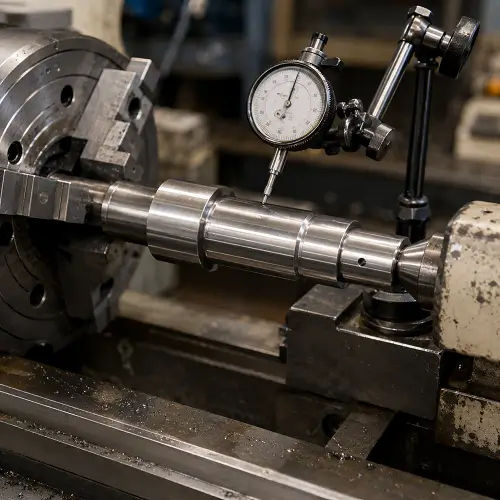
A common shop method is a dial indicator.
The usual process is:
- establish the datum or reference axis
- set the indicator on the feature to be checked
- rotate the part through 360 degrees
- observe the total indicator movement
For circular runout, the indicator checks one section at a time.
For total runout, the indicator sweeps along the full surface while the part rotates.
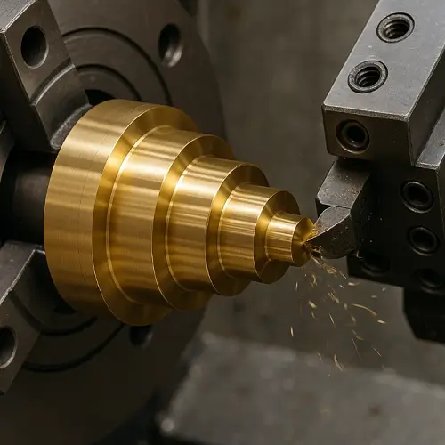
Example 2: A drill that cuts larger than its size
A shop may mount a standard drill and expect a hole close to nominal size. If the holder has radial runout, the drill can orbit slightly while spinning. The result is a hole that comes out larger than expected, even though the drill itself is the correct size. In that case, the problem is not the drill diameter. The problem is tool runout.
How to Reduce Runout in Machining
Reducing runout usually starts with the basics.
Clean and inspect contact surfaces
Chips, dirt, or damage under a holder or part seat can create runout immediately.
Improve toolholding
Use stable holders, good collets, and assemblies that match the cutting demand. The more demanding the work, the less forgiving poor tooling becomes.
Reduce setup error
Make sure the part is located and clamped from the correct reference. Re-clamping should be reviewed carefully if the feature must run true to a specific axis.
Check the datum strategy
If machining and inspection are using different logic for the datum axis, runout problems can appear even when size looks good.
Support long or flexible parts properly
Long shafts and slender rotating parts are naturally more sensitive to wobble and deflection.
Check runout before chasing size
If a hole is cutting oversize or finish is getting worse, measure runout before assuming the problem is feed, speed, or tool diameter.
How to Specify Runout Without Overcontrolling the Part
The best runout callout is the one that matches function.
If the part only needs local rotational stability at one section, circular runout is often enough.
If the whole rotating surface must stay consistent over length, total runout is usually the better choice.
The mistake is not choosing the looser symbol. The mistake is choosing the wrong one for how the feature actually works. A short local seat does not always need total runout. A long bearing journal often should not be controlled by circular runout alone.
Conclusion
Runout in machining is not just a drawing symbol and not just a spindle problem. It is a rotation problem that affects tools, parts, inspection, and final assembly. On the machining side, runout reduces tool life, hurts part quality, and creates instability. On the GD&T side, circular runout and total runout are useful only when they match the real function of the feature.
If a part includes rotating diameters, bearing seats, tapered fits, or surfaces that must run true to a datum axis, upload the drawing to JeekRapid for a machining review and quote. That review can help determine whether the issue is tool runout, part runout, or drawing control—and whether circular runout or total runout is the better choice for the part.
FAQs
What is runout in machining?
Runout is the amount of wobble or variation seen when a tool or part rotates around a reference axis.
What is the difference between circular runout and total runout?
Circular runout checks one section at a time. Total runout checks the full surface during rotation and is more restrictive.
Does runout affect hole size?
Yes. Tool runout can make a hole cut larger than expected even when the drill size is correct.
Is runout the same as roundness?
No. Roundness checks form in one cross-section. Runout checks rotational behavior relative to a datum axis.
How is runout measured?
Runout is commonly measured with a dial indicator while the part rotates about its reference axis.