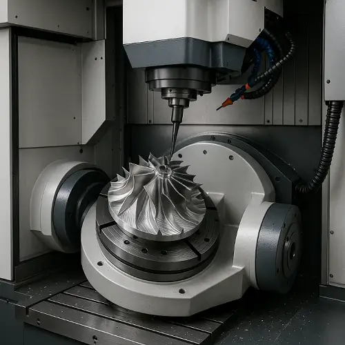
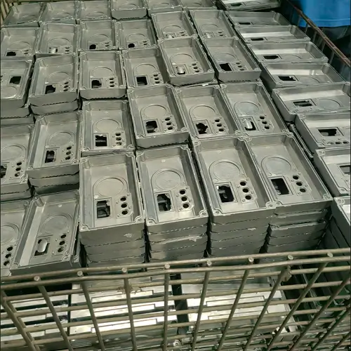
In modern manufacturing, the performance of a part depends on more than just dimensional accuracy. Even when tolerances are met, the way a surface interacts with its environment—through friction, wear, sealing, or coating adhesion—can determine whether the part succeeds or fails in service. This is why surface finish has become a critical specification across industries such as aerospace, automotive, medical devices, and precision tooling.
This article provides a complete guide to surface finish in manufacturing, covering the factors that influence it, the parameters used to describe it, common measurement techniques, and how different levels of roughness translate into real-world applications.
What Is Surface Finish?
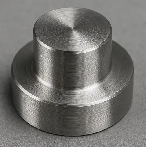
In manufacturing, surface finish (or surface roughness) refers to the small-scale deviations left on a part after machining, casting, molding, or finishing. No machined component is perfectly smooth—tool marks from turning, feed lines from milling, abrasive scratches from grinding, or even solidification patterns from casting all create microscopic peaks and valleys on the surface.
Surface finish in manufacturing is described through three aspects:
Roughness
Fine irregularities produced by the cutting tool or abrasive interaction.
Waviness
Broader undulations that result from machine vibration, tool deflection, or thermal effects.
Lay (Layer Pattern)
The predominant direction of the surface texture such as concentric layers from turning or parallel feed marks from milling.
These characteristics directly affect how a part performs. Rougher surfaces tend to increase friction and wear, while overly smooth surfaces may reduce functionality—for example, making it difficult for lubricants to adhere. Critical functions like sealing, fatigue strength, and coating adhesion all depend on specifying the correct level of roughness.
That is why in manufacturing, engineers place surface finish requirements on technical drawings alongside dimensional and geometric tolerances. A note such as Ra 1.6 µm tells machinists not only how accurate the dimensions must be, but also how smooth the finished surface should be, guiding tool choice, cutting parameters, and secondary finishing processes.
Factors Affecting Surface Finish
Machining Method
Each machining process leaves its own signature on the surface. Turning produces spiral feed marks, milling generates parallel tool paths, and drilling often shows higher roughness from tool vibration and chip evacuation. Grinding and honing deliver much finer finishes, sometimes down to 0.4 μm Ra, while polishing or lapping can achieve 0.2 μm Ra or better for sealing or optical surfaces. EDM leaves a recast layer with small craters, usually requiring secondary finishing.
Tooling and Machine Condition
Tool sharpness, geometry, and coatings directly influence finish quality. Sharp tools cut cleanly, while worn edges cause tearing and surface build-up. Machine rigidity and spindle stability are equally important—any deflection or vibration introduces waviness and chatter, degrading surface consistency.
Process Parameters
Feed rate, speed, and depth of cut strongly shape surface texture. High feed rates increase roughness, while shallow cuts with optimized speed generally improve finish. Coolant reduces friction, flushes chips, and prevents scratches, making it essential for achieving stable roughness values in machining and grinding.
Material Properties
Material behavior under cutting affects achievable finishes. Soft, ductile metals like aluminum may smear and form built-up edges, while harder steels resist cutting and can fracture microscopically. Cast materials often contain inclusions that limit achievable Ra, and heat-treated or coated parts usually require grinding or lapping to reach fine finishes.
Environment
Shop conditions also matter. Temperature changes lead to thermal drift, affecting waviness. Clean, stable coolant prevents scratching and corrosion, while external vibration or poor maintenance can degrade finish even with proper machining setups.
Surface Roughness Symbols and Parameters
Ra (Arithmetic Mean Roughness)
Ra represents the arithmetic average of surface profile deviations from the mean line. Among roughness parameters, Ra is the most widely used in engineering. Typical specifications include 3.2 μm Ra (125 μin Ra) for general machining, 1.6 μm Ra (63 μin Ra) for fine machining, and 0.8 μm Ra (32 μin Ra) or below for grinding or polishing. Ra provides a simple single-value measure, but Ra cannot distinguish between peak-dominated and valley-dominated profiles.
Rz (Mean Roughness Depth)
Rz is the average of the maximum peak-to-valley distances measured across five sampling lengths. Rz is more sensitive than Ra to scratches, burrs, or isolated irregularities. Sealing surfaces and fatigue-sensitive parts often specify Rz for better reliability.
Rmax (Maximum Roughness Depth)
Rmax, sometimes designated Rt, records the single largest peak-to-valley distance within the evaluation length. Rmax highlights the worst irregularity and is important in fatigue-critical parts, sealing areas, and surfaces requiring uniform coatings.
RMS / Rq (Root Mean Square Roughness)
RMS, or Rq, is the quadratic mean of surface deviations. Because squaring emphasizes larger deviations, Rq gives greater weight to peaks and valleys than Ra. Optical components, sealing surfaces, and precision assemblies often use Rq. For most surfaces, Rq is approximately 1.1–1.25 × Ra.
How to Measure Surface Roughness
In manufacturing, surface roughness is measured with practical tools that provide reliable data for quality control. The most common methods include:
Contact Profilometer
The most widely used device in machining workshops. A diamond-tipped stylus traces across the surface and records vertical deviations. This gives direct values for Ra, Rz, and Rmax. It is accurate, cost-effective, and suitable for most metals and hard plastics, though not recommended for very soft or delicate surfaces.
Optical Measurement
Non-contact systems, such as white-light interferometers or laser scanning microscopes, project light onto the surface and analyze reflections. These are ideal for delicate or high-precision parts where contact could damage the finish, such as optics, coatings, or semiconductors.
Replica Tape (Surface Profile Tape)
Commonly used in coating and blasting preparation, especially in industries like oil and gas. A compressible tape is pressed against the surface to capture its profile. The impression is then measured with a micrometer, providing a quick and low-cost way to verify surface roughness before painting or powder coating.
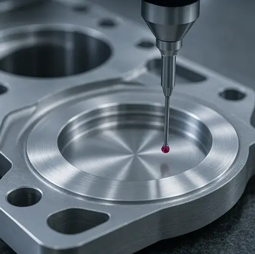
In-Process and On-Machine Probes
Modern CNC machines can integrate probing systems that check surface characteristics during or immediately after machining. While not as precise as profilometers, these methods give operators real-time feedback, reducing scrap and ensuring parts meet drawing requirements without removing them from the machine.
Surface Roughness Conversion Chart
| ISO Grade (N) | Ra (µin) | RMS (µin) | Ra (µm) | RMS (µm) |
|---|---|---|---|---|
| N12 | 2000 | 2200 | 50.0 | 55.0 |
| N11 | 1000 | 1100 | 25.0 | 27.5 |
| N10 | 500 | 550 | 12.5 | 13.8 |
| N9 | 250 | 275 | 6.3 | 6.9 |
| N8 | 125 | 138 | 3.2 | 3.5 |
| N7 | 63 | 69 | 1.6 | 1.8 |
| N6 | 32 | 35 | 0.8 | 0.9 |
| N5 | 16 | 18 | 0.4 | 0.44 |
| N4 | 8 | 8.8 | 0.2 | 0.22 |
| N3 | 4 | 4.4 | 0.1 | 0.11 |
| N2 | 2 | 2.2 | 0.05 | 0.055 |
| N1 | 1 | 1.1 | 0.025 | 0.028 |
Note: 1 µm = 39.37 µin. RMS values are approximate and depend on surface distribution and filtering.
Interpreting Roughness Values (Applications and Recommendations)
12.5–6.3 μm Ra (250–500 μin Ra, N9–N10)
Rough machining, sawing, or casting generally leaves surfaces in this range. These finishes are suitable for structural parts, pre-machining stock, or components that will undergo additional finishing. Such roughness levels are unsuitable for sealing areas, bearing contacts, or friction-critical parts.
3.2 μm Ra (125 μin Ra, N8)
Ra 3.2 μm represents the standard finish from commercial machining. Housings, brackets, and consumer components often specify this finish. Visible tool marks remain, which makes Ra 3.2 μm unsuitable for sealing interfaces or high-precision fits.
1.6 μm Ra (63 μin Ra, N7)
Ra 1.6 μm is produced by fine turning or boring. Lightly loaded moving parts, moderate bearing surfaces, and assemblies requiring closer fits frequently use this finish. Automotive and industrial machinery drawings often specify Ra 1.6 μm where cost and functionality must balance.
0.8 μm Ra (32 μin Ra, N6)
Ra 0.8 μm requires precise machining or secondary operations such as grinding. Hydraulic pistons, bearing journals, and stressed components depend on this finish for durability, sealing performance, and reduced friction. Higher processing costs make Ra 0.8 μm suitable only for function-critical surfaces.
0.4 μm Ra (16 μin Ra, N5)
Ra 0.4 μm is obtained by grinding, honing, or lapping. Critical sealing areas, high-pressure hydraulic systems, and precision assemblies specify this finish where surface quality directly controls performance. Production time and cost increase significantly at Ra 0.4 μm, so this level is reserved for mission-critical applications.
0.2 μm Ra and below (≤8 μin Ra, N4 or finer)
Ra 0.2 μm and finer surfaces result from superfinishing, lapping, or polishing. Aerospace parts, optical components, and medical implants rely on such finishes when ultra-smooth surfaces are indispensable. The cost of processing at this level makes Ra 0.2 μm appropriate only when absolutely necessary.
Choosing the Right Surface Finish in CNC Machining
CNC machining achieves tolerances down to ±0.025 mm, but surface roughness depends on tool geometry, feed rates, and finishing operations. Lower Ra values require slower feeds, finer tooling, multiple passes, or secondary processes such as grinding and lapping.
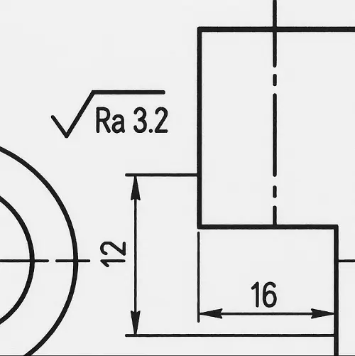
3.2 μm Ra
General machining processes yield Ra 3.2 μm. Tool marks remain visible, but this finish is sufficient for many housings, brackets, and non-critical consumer or industrial products.
1.6 μm Ra
Ra 1.6 μm delivers a smoother finish with faint tool marks. Automotive components and industrial parts commonly use this finish for assemblies that require moderate sealing and closer fits.
0.8 μm Ra
Ra 0.8 μm requires precise machining or secondary operations such as grinding or fine honing, often regarded as the starting point of precision finishing.
0.4 μm Ra
Ra 0.4 μm is obtained by precision grinding, honing, or lapping, representing a true superfinishing level suitable for aerospace seals and hydraulic parts.
0.2 μm Ra and below
Ra 0.2 μm or finer is only achieved by superfinishing techniques such as lapping and polishing, reserved for optics, implants, and other ultra-critical applications.
In engineering practice, surface finish not only affects friction coefficient and fatigue strength, but also directly determines whether components may experience galling.
Conclusion
Surface finish is a defining factor in how a part functions. Parameters such as Ra, Rz, Rmax, and RMS provide standardized ways to specify and evaluate surfaces. Conversion charts link roughness values to machining grades, while CNC practice demonstrates how each level is achieved. By choosing the correct surface finish, manufacturers ensure reliable performance, durability, and cost efficiency in production.
Surface preparation also determines the success of downstream processes such as powder coating, painting, and plating. A surface that is too rough can trap air and create voids, while an overly smooth surface may reduce coating adhesion. For powder coating in particular, finishes in the Ra 2.5–6.3 μm range often provide the right balance—enough texture for strong adhesion without compromising coating uniformity. Specifying surface finish correctly therefore improves not only machining performance but also the quality and longevity of protective coatings.
Surface finish is also influenced by anodizing, which forms a controlled oxide film on aluminum parts. Anodized aluminum surfaces typically show slightly higher roughness compared with as-machined parts because the oxide layer modifies the micro-texture. For instance, a CNC-milled surface with Ra 1.6–3.2 µm may reach Ra 2.5–4.0 µm after Type II anodizing. Type III hard anodizing creates even denser oxide films that can affect dimensional tolerances in high-precision assemblies. This relationship between surface roughness and anodizing thickness is critical in aerospace brackets, battery housings, and consumer electronics. For a detailed guide, see Anodized Aluminum: How to Anodize Aluminum Parts.
FAQ
What does 125 μin Ra mean?
125 μin Ra equals 3.2 μm Ra, ISO N8, and represents the finish from general machining.
Which is correct: Ra 3.2 μm or 3.2 μm Ra?
Both notations are correct. U.S. practice places the value first (3.2 μm Ra or 125 μin Ra), while ISO-based practice writes Ra 3.2 μm.
What is the difference between Ra and RMS?
Ra is the arithmetic mean of profile deviations, while RMS (Rq) is the quadratic mean that emphasizes peaks and valleys more strongly.
What is a good Ra value for machining?
3.2–1.6 μm Ra is standard for general machining. 0.8 μm Ra or better is required for hydraulic parts, bearings, and precision fits.
How is surface finish measured?
Contact profilometers and optical instruments measure Ra, Rz, Rmax, and RMS according to ISO and ASME standards.
Why does surface finish matter in coating or plating?
Adhesion and appearance depend on substrate roughness. Moderate roughness promotes bonding, while excessive irregularities show through coatings.

