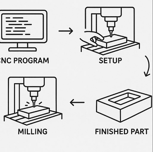
Milling plays a central role in manufacturing, offering the flexibility to create flat surfaces, precision slots, and high-accuracy complex 3D contours. The process uses a rotating multi-point cutting tool to remove material in controlled increments, making it suitable for metals, plastics, and composite materials. In modern CNC milling, advanced motion control, precise machine setups, and optimized tooling strategies enable manufacturers to achieve tight tolerances and consistent surface quality—whether producing a single prototype or thousands of identical parts. This article explores milling processes, operations, tooling, cutting parameters, and real-world applications, providing engineers and clients with the practical information needed to plan and execute efficient milling operations.
What Is Milling?
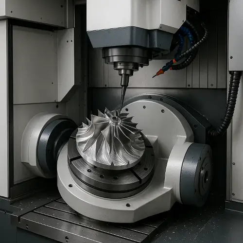
Milling is a material removal process in which a rotating multi-point cutting tool advances into a stationary workpiece to remove material in the form of chips. This technique is widely used in manufacturing for creating flat surfaces, slots, contours, and complex 3D shapes.
In CNC milling, computer-controlled motion ensures high repeatability and accuracy, enabling production of prototypes, low-volume parts, and large-scale manufacturing runs.
Common Milling Processes
-
Face Milling – Produces flat surfaces perpendicular to the spindle axis.
-
Peripheral Milling – Removes material along the outer circumference of the cutter.
-
Slot Milling – Cuts grooves with defined width and depth.
-
Contour Milling – Follows complex profiles and 3D surfaces.
-
Pocket Milling – Clears material inside enclosed boundaries.
These processes are adaptable for milling process in manufacturing across metals, plastics, and composites.
Types of Milling Operations
-
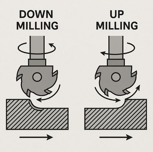
Climb Milling (Down Milling) – The cutter rotates in the same direction as the feed, producing smoother finishes and reducing tool wear.
-
Conventional Milling (Up Milling) – The cutter rotates opposite to the feed, improving stability but increasing tool wear.
Vertical vs Horizontal Milling
-
Vertical Milling – Spindle is vertical, ideal for detailed work, die-sinking, and mold making.
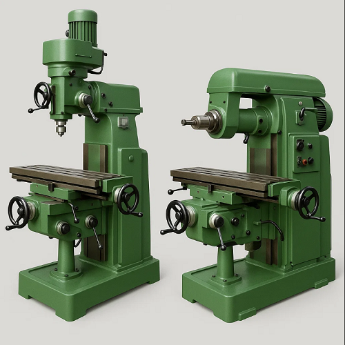
-
Horizontal Milling – Spindle is horizontal, suited for heavy cuts and better chip evacuation.
Difference between vertical and horizontal milling is often determined by production volume, part geometry, and chip removal efficiency.
Milling Tools and Cutters
| Tool Type | Common Use | Tool Material |
|---|---|---|
| End Mill | Profiles, slots, plunging | Carbide / HSS |
| Face Mill | Large flat surfaces | Carbide inserts |
| Ball Nose Cutter | 3D contouring | Carbide |
| Slab Mill | Heavy stock removal | HSS |
| Form Cutter | Specialized profiles | Carbide |
Milling Parameters & Calculations
Cutting Speed (Vc):
Vc=π×D×RPM/1000V_c = \pi \times D \times \text{RPM} / 1000
Feed Rate (F):
F=RPM×z×fzF = \text{RPM} \times z \times f_z
Example: Ø10 mm cutter, 3000 RPM, 4 teeth, 0.05 mm/tooth → 600 mm/min feed rate.
Recommended Cutting Speeds by Material
| Material | Machinability (%) | Cutting Speed (m/min) | Tool Recommendation |
|---|---|---|---|
| Aluminum 6061 | 300% | 250–350 | Carbide |
| Mild Steel 1018 | 160% | 90–120 | HSS / Carbide |
| Stainless Steel 304 | 50% | 50–80 | Coated Carbide |
| Titanium Grade 5 | 30% | 30–50 | Coated Carbide + Coolant |
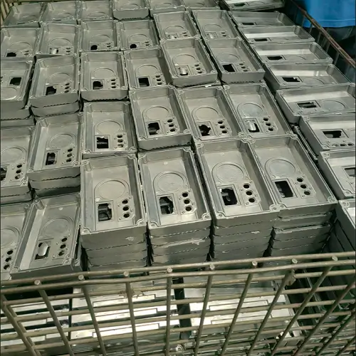
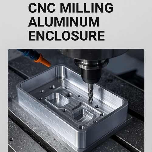
Engineering Case Study: CNC Milling of Aluminum Housing
A client required CNC milling aluminum housing for an automotive application, tolerances within ±0.01 mm. JeekRapid selected a vertical CNC milling machine with carbide end mills, flood coolant, and climb milling strategy.
Parameters used:
-
Cutting speed: 280 m/min
-
Feed per tooth: 0.12 mm
-
Depth of cut: 1.5 mm per pass
Results:
-
Cycle time: 18 minutes per part
-
Surface roughness: Ra 0.8 µm
-
Dimensional variation: ±0.008 mm
This example shows how optimizing parameters and tool selection ensures high accuracy and surface finish.
Fixtures and Workholding
-
Vise Clamping – For general-purpose work.
-
Fixture Plates – For repeatable setups.
-
Vacuum Tables – For thin or delicate parts.
-
Custom Soft Jaws – For irregular profiles.
Coolant and Lubrication
-
Flood Coolant – For heat control in heavy milling.
-
MQL – Minimal coolant for clean operations.
-
Air Blast – Chip removal in dry cutting.
Common Milling Defects and Troubleshooting
| Defect | Cause | Solution |
|---|---|---|
| Chatter | Excessive tool overhang | Reduce stick-out |
| Poor Finish | Incorrect feed/speed | Adjust parameters |
| Tool Wear | Inadequate cooling | Improve coolant flow |
Milling vs Other Processes
| Process | Precision | Surface Finish | Use Case |
|---|---|---|---|
| Milling | ±0.01 mm | Good | Complex parts |
| Grinding | ±0.005 mm | Excellent | Finishing |
| EDM | ±0.002 mm | Very good | Hardened metals |
How to Choose the Right Milling Method
-
Identify Material – Aluminum allows higher speeds; stainless steel needs coated carbide and coolant.
-
Select Tool Geometry – End mill for slots, face mill for surfacing, ball nose for contours.
-
Pick Milling Direction – Climb milling for better finish; conventional milling for stability.
-
Choose Machine Type – Vertical for precision and setup ease; horizontal for high removal rates.
-
Adjust Parameters – Match feed and speed to balance productivity and tool life.
Applications of Milling
-
Aerospace – Structural parts, housings.
-
Automotive – Engine and gearbox components.
-
Medical – Prosthetic and surgical tools.
-
Tooling – Mold bases, dies, jigs.
Internal Link
For detailed machine classifications, see Milling Machine Guide.
Request a Quote for Your Milling Pro
Whether you need a precision prototype or a large production run, JeekRapid delivers CNC milling services with tight tolerances, consistent quality, and flexible material options. Upload your drawings or specifications to receive a detailed manufacturing quote and lead time asse
FAQ
Q1: What is milling in manufacturing?
A: Milling is a subtractive machining process that removes material using a rotating cutter.
Q2: What is the difference between vertical and horizontal milling?
A: Vertical has the spindle upright for precision work; horizontal offers better chip evacuation for heavy cutting.
Q3: Why use climb milling in CNC machining?
A: It provides better surface finish, reduced burr formation, and longer tool life.