Flanges are used across nearly every industry where fluid, gas, or mechanical interfaces require a secure and serviceable connection. Their structure allows equipment and piping to be assembled with predictable alignment and later disassembled for maintenance or inspection. Different types of flanges exist to meet specific design and pressure requirements, and choosing the right one often depends on installation method, material compatibility, and sealing surface conditions.
Understanding the purpose, structure, and machining of flanges is essential in both design and manufacturing stages—especially in systems that demand long-term reliability under variable loads and temperatures.
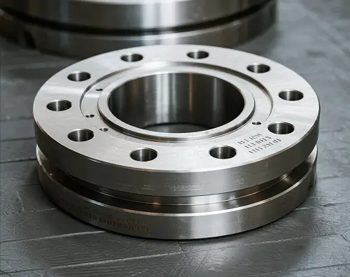
What Is a Flange?
A flange is a mechanical component used to connect pipes, valves, pumps, or structural elements in a piping system. It enables disassembly and maintenance without cutting or welding the pipeline. By bolting two flanges together with a gasket in between, engineers can create a secure, leak-resistant joint that withstands internal pressure and mechanical stress.
Flanges are essential in industries like oil and gas, power generation, water treatment, HVAC, and chemical processing. Available in various materials, pressure ratings, and sizes, they allow for flexible and modular system design.
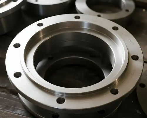
Common Types of Flanges and Their Uses
Selecting the correct flange type ensures structural integrity, ease of installation, and compatibility with operational loads. Below are the most widely used flange types.
Weld Neck Flange (WN)
This flange features a long, tapered hub and is butt-welded to the pipe. It provides excellent stress distribution and is ideal for high-pressure, high-temperature systems.
- Applications: Oil and gas pipelines, power plants
- Installation: Requires precision welding
- Standards: ASME B16.5, typically 1/2″ to 60″
Slip-On Flange (SO)
The pipe slides into the flange bore and is welded on both sides. It’s cost-effective but less robust under cyclic loads.
- Applications: Cooling systems, low-pressure fluid transfer
- Installation: Double fillet weld
Blind Flange (BL)
A solid flange used to seal pipe ends. Useful for pressure testing and future system extensions.
- Applications: Isolation points, test ports
- Design Note: Must handle internal pressure like a standard pipe section
Threaded Flange (TH)
Internally threaded to fit onto externally threaded pipes. Requires no welding, suitable for explosive environments.
- Applications: Low-pressure, flammable service areas
- Limitation: Thread strength limits pressure rating
Socket Weld Flange (SW)
The pipe fits into a socket in the flange. Provides a smooth bore and strong connection for small-bore systems.
- Applications: Chemical processing, instrumentation lines
- Note: A small expansion gap should be left during welding
Lap Joint Flange (LJ)
Used with a stub end, allowing rotation for bolt alignment. Common in systems requiring frequent disassembly.
- Applications: Corrosive or sanitary systems
- Cost Benefit: Only the stub end must be corrosion-resistant
Flange Type Comparison
| Flange Type | Pressure Suitability | Welding Required | Typical Application | Alignment Flexibility |
|---|---|---|---|---|
| Weld Neck | High | Yes | Power, oil & gas pipelines | Low |
| Slip-On | Low to Medium | Yes | Cooling systems, low-pressure piping | Low |
| Blind | High | No | End-of-line sealing, pressure testing | – |
| Threaded | Low | No | Small bore, explosive environments | Low |
| Socket Weld | Medium to High | Yes | Instrumentation, process systems | Low |
| Lap Joint | Low to Medium | No (stub welded) | Corrosive or frequently serviced lines | High |
Dimensional Considerations
When designing with flanges, engineers must evaluate:
- Flange thickness and diameter
- Bolt circle diameter (BCD) and hole count
- Raised face (RF) or flat face (FF) compatibility
- Gasket selection based on pressure, temperature, and fluid
Standards like ASME B16.5 and EN 1092-1 govern these dimensions, ensuring interchangeability and reliability.
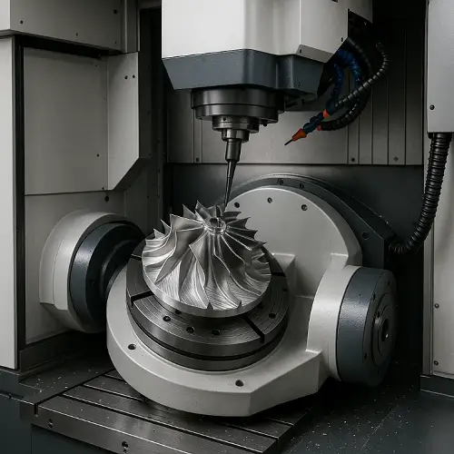
What Is Flange Machining?
Flange machining refers to the precision processes used to manufacture or finish flanges, whether as standalone components or integral pipe ends. Accurate machining ensures flatness, alignment, and surface integrity—critical for sealing and structural performance.
Flange machining may involve rough turning from forged blanks, drilling bolt holes, surfacing the flange face, and applying specific finishes or tolerances based on design standards.
CNC Flange Machining: Process Overview
Modern flange machining relies heavily on CNC equipment for accuracy and repeatability. The typical machining process includes:
Facing
Machining the flange face to ensure proper gasket seating and surface finish (e.g., serrated or smooth finish).
Drilling and Tapping
Bolt holes are drilled precisely according to the specified bolt pattern. Threads may be added when using threaded flanges.
Grooving
In some cases, flanges require ring-type joint (RTJ) grooves or custom gasket channels.
Turning
The OD (outer diameter), hub profile, or sealing faces may require additional turning operations to meet dimensional tolerances.
Materials Used in Flange Manufacturing
Material selection depends on application requirements, such as pressure, corrosion resistance, and temperature. Common materials include:
- Carbon Steel: Economical, suitable for oil, gas, and water systems
- Stainless Steel (304, 316): Excellent corrosion resistance
- Alloy Steel (A182 F11/F22): For high-temperature or pressure
- Duplex Stainless Steel: Balanced strength and corrosion resistance
- Aluminum or Brass: Lightweight, for low-pressure systems
Tolerances, Standards, and Surface Finish
Precision matters in flange machining. Typical requirements include:
- Dimensional Tolerances: Usually per ASME B16.5 or customer-specific drawings
- Surface Roughness: Raised face finish often Ra 3.2–6.3 μm
- Flatness: Critical for sealing; often measured across gasket seating surface
- Inspection: Visual, dimensional, and sometimes pressure or ultrasonic testing
Flange Machining Tolerances & Surface Specs
| Feature | Typical Requirement | Standard Reference |
|---|---|---|
| Face Flatness | ≤ 0.13 mm (≤ 5 thou) | ASME B16.5 |
| Surface Roughness (RF) | Ra 3.2–6.3 μm (125–250 μin) | ASME B46.1 |
| Bolt Hole Positional Tolerance | ±0.5 mm | Customer Drawing / EN 1092 |
| Bore Concentricity | ≤ 0.2 mm | Internal QC Spec |
Typical Applications of Precision-Machined Flanges
- Oil & Gas: Pipe joints, valve connections
- Water Treatment: Pump flanges, access points
- Pharmaceutical: Sanitary flanges, easy to clean
- HVAC: Ducting systems and modular assemblies
- Marine & Offshore: Corrosion-resistant flange joints
Frequently Asked Questions About Flanges
Q: What’s the difference between a raised face and a flat face flange?
A raised face (RF) concentrates pressure on the gasket, improving sealing. A flat face (FF) provides full-surface contact and is typically used in low-pressure systems.
Q: Can flanges be re-machined after installation?
Yes, in some cases, flanges can be resurfaced if they have become scratched or warped, but only if there’s enough material thickness.
Q: What is the standard bolt pattern for flanges?
Bolt patterns vary by flange size and standard (ASME, EN, DIN). Refer to the standard tables or drawings for correct dimensions.
Q: Do flange faces need surface treatment?
It depends. Stainless steel may not need coating, but carbon steel flanges often require passivation, painting, or plating to prevent corrosion.
Q: How do I choose the correct flange material?
Consider pressure, temperature, corrosion exposure, and compatibility with the piping system. For harsh conditions, stainless or duplex steels are common choices.
click here to request a quote. Engineers will assess dimensions, material, and surface specs before issuing a response.