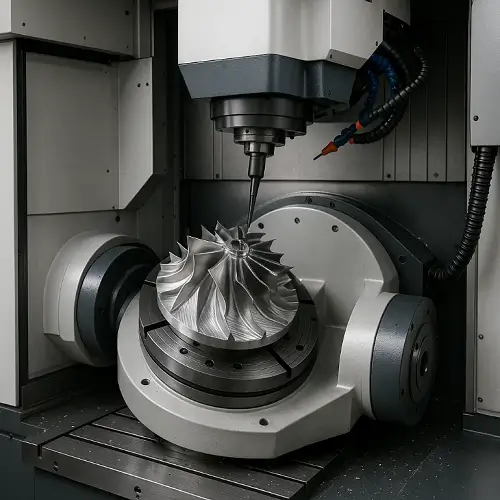
Machined surface roughness describes the small peaks and valleys left on a part after CNC milling, turning, grinding, or another manufacturing process. These irregularities may be difficult to see, but they can affect sealing, friction, wear, coating adhesion, appearance, and how two parts fit together.
Surface roughness is usually specified with a value such as Ra 3.2 μm, Ra 1.6 μm, or 125 μin Ra. A lower Ra value represents a smoother surface, but smoother is not automatically better. Fine surface requirements take more machining time and may require grinding, honing, lapping, or polishing.
The right machined surface finish depends on what the surface needs to do. A hidden face on an aluminum bracket does not need the same finish as a hydraulic sealing surface, bearing journal, sliding shaft, or visible product housing.
What Is Machined Surface Roughness?
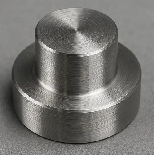
Machined surface roughness is the fine texture created when a cutting tool or abrasive contacts the workpiece. CNC milling leaves tool paths, turning creates a directional feed pattern, and grinding produces much smaller abrasive marks.
Even a surface that looks smooth still contains microscopic variations. A surface roughness measurement converts those variations into a numerical value that can be shown on a drawing and checked during inspection.
Surface roughness should not be confused with dimensional tolerance. A shaft may meet its diameter tolerance but still have an unacceptable rough surface. The opposite is also possible: a surface can be very smooth while the diameter, flatness, or position is outside the required tolerance.
This distinction matters when requesting CNC parts. The drawing should define dimensional accuracy and surface roughness separately because they control different aspects of the finished component.
What Is the Difference Between Surface Roughness and Surface Finish?
Surface roughness and surface finish are often used as if they mean the same thing, especially in everyday machining discussions. They are related, but they are not technically identical.
Surface roughness refers to the closely spaced microscopic irregularities on a surface. These irregularities are measured with parameters such as Ra, Rz, Rq, or Rt.
Surface finish is a broader term describing the overall condition of the surface. It includes roughness, waviness, and lay.
Waviness consists of more widely spaced surface variations. It may result from vibration, tool deflection, heat, machine movement, or an unstable setup. A part can have acceptable roughness but still show visible waves caused by chatter.
Lay describes the main direction of the surface pattern. Turning usually leaves a circular or helical lay, while face milling may produce curved or crossing tool marks. Lay can affect sealing, sliding contact, lubrication, and appearance.
For most ordinary CNC drawings, the surface finish requirement is expressed using an Ra value. For sealing surfaces, bearing areas, sliding contacts, or other sensitive features, additional parameters or lay requirements may be necessary.
What Do Ra, Rz, Rq, and RMS Mean?
Ra is the most commonly specified surface roughness parameter, but it does not describe every surface characteristic. Two surfaces can have the same Ra value while having different scratches, peaks, valleys, or directional patterns.
| Parameter | What it describes | When it is useful |
|---|---|---|
| Ra | The arithmetic average of profile deviations from the mean line | General CNC machining and routine surface finish requirements |
| Rz | The vertical height between significant peaks and valleys under the applicable measurement standard | Surfaces where scratches, valleys, sealing, or local defects matter |
| Rq or RMS | The root mean square of profile deviations, giving greater weight to larger variations | Older drawings, optical work, and specifications that use RMS rather than Ra |
| Rt | The total height between the highest peak and deepest valley across the evaluation length | Finding the largest overall surface variation |
| Rmax | A maximum roughness value found on some older drawings | Must be interpreted using the standard named on the drawing |
Ra Surface Finish
Ra stands for arithmetic average roughness. It calculates the average distance of the measured roughness profile from its mean line.
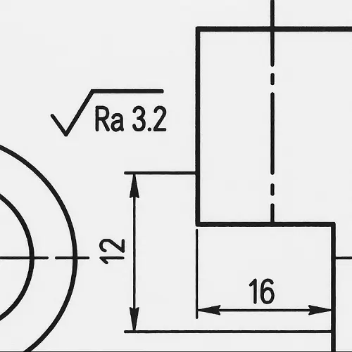
Ra is popular because it provides a single value that is easy to specify and compare. General CNC machining may use Ra 3.2 μm, while a more controlled surface may require Ra 1.6 or Ra 0.8 μm.
Ra can hide isolated defects because it is an average. A deep scratch may not change the average enough to show how serious the defect is. Visual requirements and additional parameters may therefore be needed for cosmetic or function-critical parts.
Rz Surface Finish
Rz focuses more on the vertical difference between peaks and valleys. It is more sensitive than Ra to deeper scratches and pronounced surface features.
This can make Rz useful for sealing surfaces, sliding components, fatigue-sensitive areas, and surfaces where isolated valleys may hold fluid or create leakage paths.
The exact definition and evaluation method depend on the standard specified on the drawing. An Rz value should not be interpreted without checking whether the project follows an ISO, ASME, customer, or older drawing standard.
RMS and Rq Surface Finish
Rq is the root mean square roughness and is commonly referred to as RMS surface finish. Because the calculation gives more weight to larger deviations, Rq is usually higher than Ra on the same measured profile.
There is no universal conversion that can accurately change every Ra value into RMS or Rq. The relationship depends on the actual shape of the surface profile. If a drawing specifies 125 RMS, it should not automatically be treated as 125 Ra.
How Do You Read a Surface Finish Chart?
A surface finish chart compares roughness values in microinches and micrometers. In U.S. drawings, roughness is often expressed in microinches, written as μin. Metric drawings normally use micrometers, written as μm.
One micrometer equals approximately 39.37 microinches. A 125 μin Ra finish is therefore approximately equal to Ra 3.2 μm.
The following machining surface finish chart provides practical reference values. These are planning ranges rather than guarantees. The achievable result depends on the material, tool, cutting parameters, machine condition, workholding, geometry, and measurement method.
| Surface finish in μin Ra | Metric value in μm Ra | Typical surface condition | Common manufacturing approach |
|---|---|---|---|
| 500 | 12.5 | Rough surface with clearly visible marks | Sawing, casting, or rough machining |
| 250 | 6.3 | Rough machined finish | Heavy turning or milling |
| 125 | 3.2 | General as-machined CNC finish | Standard CNC milling or turning |
| 63 | 1.6 | Fine machined finish with lighter tool marks | Controlled milling, turning, or boring |
| 32 | 0.8 | Smooth precision finish | Fine turning or grinding |
| 16 | 0.4 | Very smooth functional finish | Grinding, honing, or lapping |
| 8 | 0.2 | Fine precision surface | Fine grinding, lapping, or polishing |
A surface finish chart does not mean that every machining process automatically produces the value shown. A stable turning operation may achieve Ra 0.8 μm on one shaft, while a thin or vibration-prone component may struggle to maintain Ra 1.6 μm.
The table should therefore be used to understand the level of finish being requested, not as a replacement for reviewing the actual part.
What Does a 125 Surface Finish Mean?
A 125 surface finish normally refers to 125 microinches Ra in U.S. manufacturing. It is approximately equal to Ra 3.2 μm.
This is a common as-machined surface finish for CNC-milled and turned parts. Light tool marks may remain visible, but the surface is generally suitable for brackets, housings, covers, mounting faces, fixtures, and other parts without demanding friction or sealing requirements.
A 125 finish does not mean the surface must be polished or visually flawless. It controls measured roughness rather than color, gloss, scratches, burrs, dents, or other appearance defects.
If a drawing only says “125 finish” without identifying Ra, RMS, the unit, or the applicable standard, the requirement should be confirmed before production. A 125 μin Ra requirement is not the same as 125 μm, and 125 RMS should not automatically be treated as 125 Ra.
Similar logic applies to other common callouts. A 63 μin Ra finish is approximately Ra 1.6 μm, while 32 μin Ra is approximately Ra 0.8 μm. Values of 16 and 8 μin Ra correspond to approximately Ra 0.4 and Ra 0.2 μm.
These values describe progressively smoother surfaces, but each step can require more controlled machining, additional inspection, or a secondary finishing process.
What Surface Finish Can CNC Machining Achieve?
General CNC milling and turning commonly produce surfaces around Ra 3.2 μm, equivalent to approximately 125 μin Ra. This is a practical finish for many noncritical faces and is often available without a separate finishing operation.
Ra 1.6 μm, or approximately 63 μin Ra, can often be achieved with a stable machine, sharp tool, controlled feed, suitable material, and a dedicated finishing pass. This finish is useful for closer fits, improved appearance, and surfaces that require less friction than a standard as-machined finish.
Ra 0.8 μm, or approximately 32 μin Ra, is more demanding. Fine turning may achieve it on suitable cylindrical parts, but geometry, material, rigidity, and tool condition become more important. Milling may need a carefully planned finishing toolpath, and some features may require grinding.
Ra 0.4 μm and smoother normally require a specialized finishing process. Grinding, honing, lapping, or polishing may be selected depending on whether the feature is flat, cylindrical, internal, or cosmetic.
Milling Surface Finish
Milling surface roughness is influenced by feed per tooth, cutter geometry, tool runout, spindle condition, toolpath direction, material, and vibration. A large flat face can show visible tool paths even when its measured Ra value is acceptable.
Reducing feed can improve the milling surface finish, but extremely light cutting is not always effective. If the tool rubs instead of cutting cleanly, the surface may become worse. A sharp finishing tool and stable workholding usually matter more than simply lowering the feed rate.
Ball-end milling of curved surfaces also behaves differently from face milling. Step-over distance influences the height of the remaining scallops, so a smooth-looking 3D surface may require a smaller step-over and longer machining time.
Turning Surface Finish
Turning usually produces a predictable pattern because the tool moves along a rotating workpiece. Feed rate, nose radius, tool sharpness, material behavior, and machine stability all affect the final roughness.
Shafts, bushings, pins, and sleeves can often achieve a fine surface directly from turning. If the part requires tighter diameter control, better roundness, or a smoother sealing surface, centerless grinding may be added after turning.
Grinding Surface Finish
Grinding removes material with abrasive grains rather than a single cutting edge. It is commonly used when a feature needs better flatness, roundness, diameter control, or surface roughness than ordinary milling or turning can provide.
Flat plates, mold components, spacers, and precision mounting faces may use surface grinding to improve flatness and finish. Cylindrical and centerless grinding are more appropriate for shafts, pins, and round outside diameters.
Grinding does not automatically guarantee a perfect surface. Wheel selection, dressing, coolant, material hardness, feed, and heat control still affect the result. Poor grinding conditions can create chatter, scratches, or grinding burn even when the average Ra value appears acceptable.
How Is Surface Finish Measured?
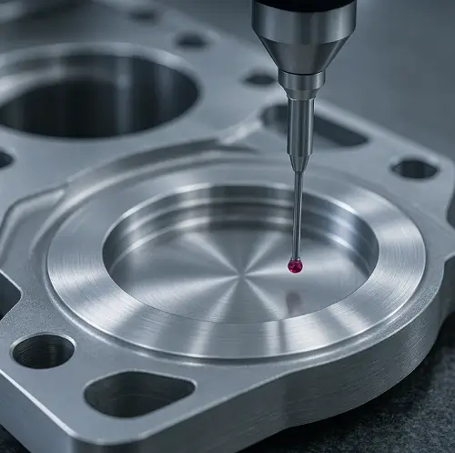
Surface finish measurement is most commonly performed with a contact profilometer. A small stylus moves across the part and records the vertical movement caused by microscopic peaks and valleys.
The instrument filters the measured profile and calculates parameters such as Ra, Rz, Rq, or Rt. The result depends on the selected cutoff, evaluation length, filter, stylus condition, measurement direction, and applicable standard.
Measurement direction matters because machined surfaces have lay. A stylus is normally moved across the dominant surface pattern rather than along it. Measuring in a different direction can produce a different result on the same part.
The surface must also be clean. Coolant residue, dirt, dust, oil, loose abrasive particles, or burrs can interfere with the stylus and produce misleading readings.
Optical surface measurement may be used when the part is too delicate, too small, too soft, or difficult to reach with a contact stylus. Optical systems can also provide a three-dimensional view of the surface, but the equipment and measurement method must still suit the material and specification.
Surface roughness comparator plates provide a quick visual and tactile reference in a workshop. They are useful for estimating whether a surface is close to a known milling, turning, or grinding finish. They should not replace instrument measurement when the drawing contains a controlled roughness requirement.
What Surface Finish Standards Apply to CNC Parts?
Surface roughness values only become reliable requirements when the drawing identifies the parameter, unit, limit, and applicable standard.
For U.S.-based drawings, ASME B46.1-2019 (R2026) defines surface texture terms and parameters, including roughness, waviness, and lay. ASME Y14.36 provides surface texture symbols used on engineering drawings.
For ISO-based drawings, ISO 21920-1:2021 covers the indication of profile surface texture on technical documentation. ISO 21920-2:2021 defines terms and surface texture parameters, while ISO 21920-3:2021 addresses how surface texture specifications are evaluated.
Older drawings may still reference ISO 1302 or ISO 4287. These standards have been withdrawn and replaced by the ISO 21920 series, but they may remain contractually relevant when named on an existing customer drawing. The manufacturer should not silently reinterpret an older requirement using a newer standard without confirmation.
A clear surface finish requirement should identify the necessary parameter and unit. For example, Ra 1.6 μm maximum is much clearer than simply writing smooth finish.
The drawing may also state the machining method, lay direction, sampling conditions, or whether material removal is required or prohibited. These details are usually necessary only when the surface has a specific functional role.
How Does Surface Roughness Affect CNC Machining Cost?
A lower Ra requirement usually increases CNC machining cost because the surface needs more control. The machine may require a slower finishing pass, a sharper or specialized tool, reduced step-over, more stable workholding, and additional inspection.
Ra 3.2 μm is often economical because it can be produced as part of ordinary CNC milling or turning. Ra 1.6 μm may require a dedicated finishing operation but can still be achieved directly on many suitable features.
Ra 0.8 μm or Ra 0.4 μm can change the manufacturing plan. The part may need grinding, honing, lapping, polishing, or a different machining sequence. These processes add setup, handling, inspection, and lead time.
Surface area also matters. Producing Ra 0.8 μm on one small bearing seat is different from applying the same requirement to every surface of a large housing. A broad roughness callout can increase cost even when most surfaces do not need it.
Part geometry can make a seemingly ordinary requirement expensive. A flat external face is easier to finish and measure than a deep pocket, small internal bore, narrow groove, thin wall, or complex curved surface.
Inspection adds another cost. If every part must have a recorded surface roughness result, measurement time and documentation need to be included in the quote. Critical features should therefore be identified clearly rather than applying the tightest finish to the entire component.
How Do You Choose Surface Finish Requirements for a CNC Part?
Start with the function of each surface. If a surface only forms the outside of a bracket or hidden housing, Ra 3.2 μm may be sufficient. Specifying a finer finish may add cost without improving the part.
Visible surfaces may need more than a roughness value. Tool-path consistency, scratches, gloss, color, anodizing, bead blasting, or polishing can affect appearance even when Ra meets the drawing.
Sliding and bearing surfaces may require Ra 1.6 or Ra 0.8 μm, depending on speed, load, material, lubrication, and wear requirements. The correct value should come from the assembly and operating conditions rather than from a general chart.
Sealing surfaces need careful review because an extremely smooth surface is not always ideal. The seal type, pressure, fluid, material, flatness, lay direction, and valley structure can all influence leakage. Ra alone may not fully describe performance.
Coating and bonding surfaces may require enough texture for adhesion. Polishing the surface unnecessarily can reduce mechanical bonding, while an excessively rough surface may remain visible through a thin coating.
Only function-critical surfaces should receive demanding roughness callouts. The 2D drawing should mark those locations clearly and state the parameter, value, unit, and standard. If the requirement applies only to one sealing face, shaft diameter, bearing bore, or visible panel, it should not be applied to the entire part.
Conclusion
Machined surface roughness describes the microscopic texture left by milling, turning, grinding, and other manufacturing processes. It affects friction, sealing, wear, appearance, coating adhesion, and the way parts interact in an assembly.
Ra is the most common general roughness parameter. Rz, Rq, RMS, Rt, and other parameters provide additional information when peaks, valleys, or isolated defects matter. A 125 surface finish normally means 125 μin Ra, which is approximately equal to Ra 3.2 μm and is common for general CNC machining.
Lower roughness values require more manufacturing control. Ra 1.6 μm may be achievable with fine machining, while Ra 0.8 or Ra 0.4 μm may require grinding or another secondary process. The best surface finish is not the lowest number—it is the finish that supports the part’s function without adding unnecessary machining cost.
Upload your CAD model and 2D drawing to Get a CNC Machining Quote. JeekRapid can review the material, critical surfaces, Ra or Rz requirements, machining process, inspection needs, quantity, and finishing options before production.